General Information
Figure 1 shows a suspension bridge that is used by motorcycles, bicycles and pedestrians.
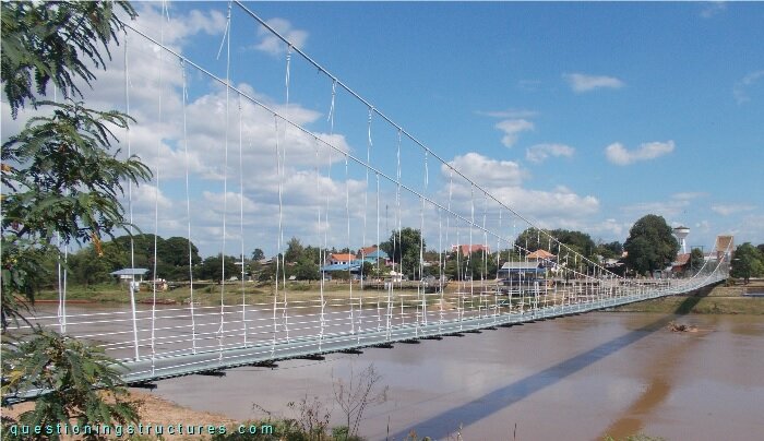
| Type | Single-span suspension bridge |
| Main span | ≅ 250 m |
| Deck width | ≅ 2 m |
| Deck width to main span ratio | ≅ 1:125 |
| Pylon | Reinforced concrete |
| Girder | Steel transverse beam |
Sag to Main Span Ratio
Figure 2 shows a side view of the main span.
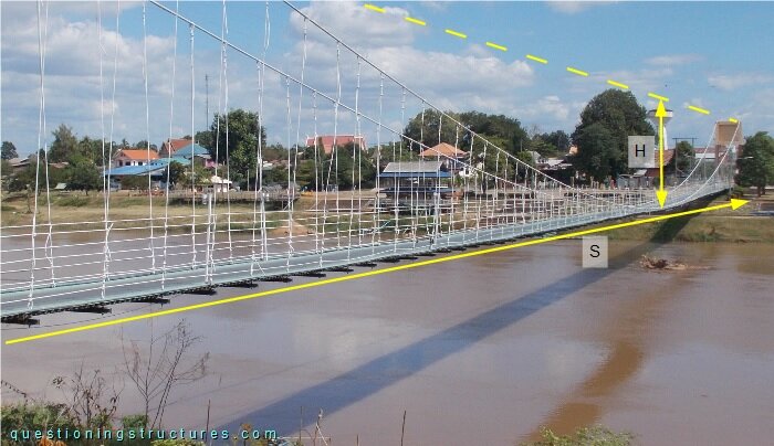
The sag s ≅ 10 m, and the main span m ≅ 250 m; that gives a sag to main span ratio of 1/25. Figure 3 shows a schematic cross-section of the bridge.
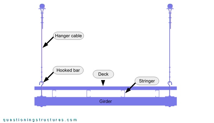
The girder consists of two side-by-side placed U-sections, while the stringers and deck are made of lipped channels. The hanger cables are connected to the girder by hooked bars, plates, and nuts. Plan bracing is not installed. Figure 4 shows a pylon.
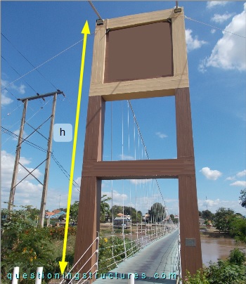
The pylon has a height over the deck of h ≅ 10 m, which is the same height as the sag. Consequently, the main cables and the deck are about at the same elevation level in the mid-span region, as shown in figure 5.
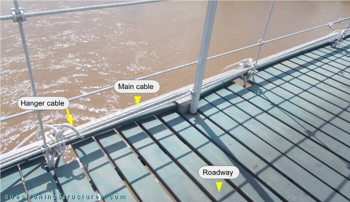
The main cables and hooked bars are directly connected; the hanger cables are wrapped around them and fixed by U-bolt clamps. Figure 6 shows two schematic lateral views.
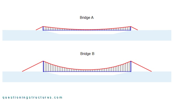
Bridge A is the above shown bridge; the sag to main span ratio is 1:25, and the pylon height over the deck is about 10 m. Bridge B has a sag to main span ratio of 1:10, and the pylon height over the deck is 26 m (25 m + 1 m hanger cable length in the mid-span region). The remaining bridge layout (e.g., main span, hanger cable spacing, back main cable inclination, etc.) and materials are equal on both bridges.
What are the main points of efficiency comparison between the two bridges? Who determines the weight of those points in a weighted decision matrix?