General Information
Figure 1 shows a pedestrian suspension bridge.
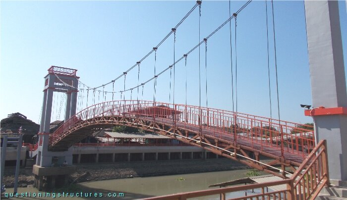
| Type | Single-span suspension bridge |
| Main span | ≅ 35 m |
| Deck width | ≅ 2 m |
| Deck width to main span ratio | ≅ 1:17 |
| Pylon | Reinforced concrete |
| Girder | Steel arch truss |
Steel Arch Truss
Figure 2 shows a schematic lateral view of the bridge.
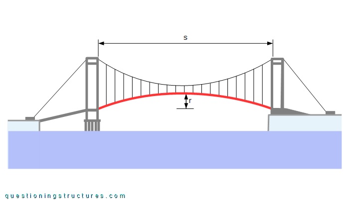
The arch rise r ≅ 2 m, and the main span s ≅ 35 m; that gives an arch rise to main span ratio of about 1/17. Figure 3 shows an arch truss sector.
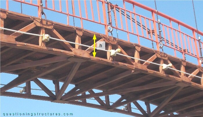
The truss height h ≅ 0.4 m, and the truss members are made of rectangular hollow sections. Figure 4 shows a schematic lateral view of the bridge without the suspension structure.
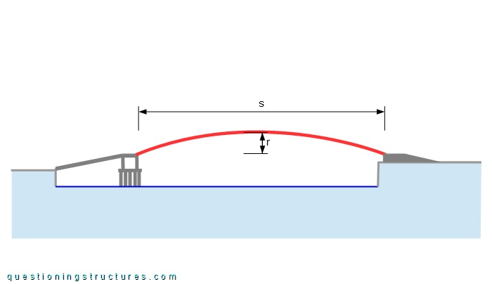
Assume that the arch truss is of type two-hinged.
Gusset Plates
Figure 5 shows an arch truss sector.
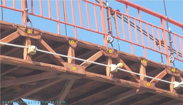
The gusset plates (marked by the letter G) are welded on the upper chord nodes and alternating on the bottom chord nodes.
Are the gusset plates required for structural reasons?