General Information
Figure 1 shows a suspension bridge that is used by motorcycles, bicycles and pedestrians.
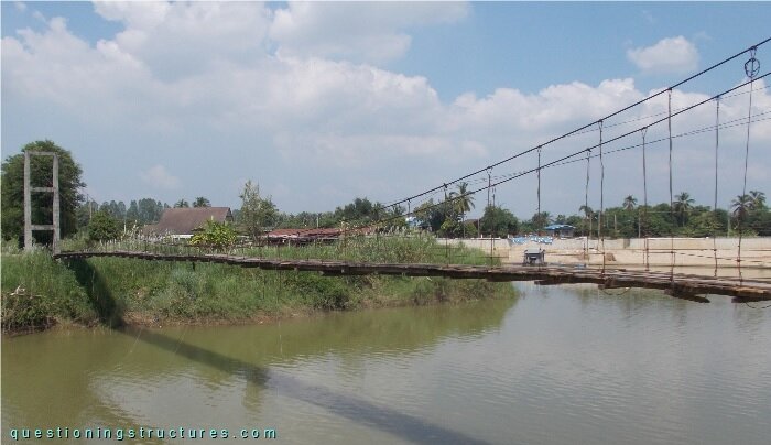
| Type | Single-span suspension bridge |
| Main span | ≅ 70 m |
| Deck width | ≅ 1.5 m |
| Deck width to main span ratio | ≅ 1:46 |
| Pylon | Reinforced concrete |
| Girder | Timber transverse beam |
Hanger Cable to Timber Girder Connection
Figure 2 shows a schematic cross-section of the bridge.
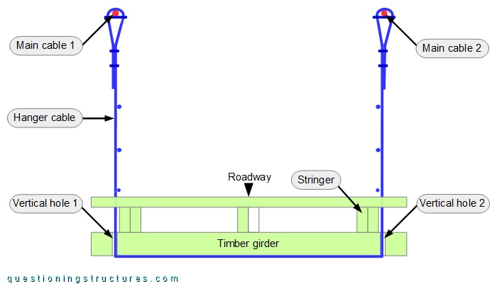
A single hanger cable runs from main cable 1 to main cable 2 via the girder bottom side. The hanger cable passes through the girder through two vertical holes. The forces are transferred by direct (cable to girder) contact. Figure 3 shows a hanger cable to girder connection viewed from below.
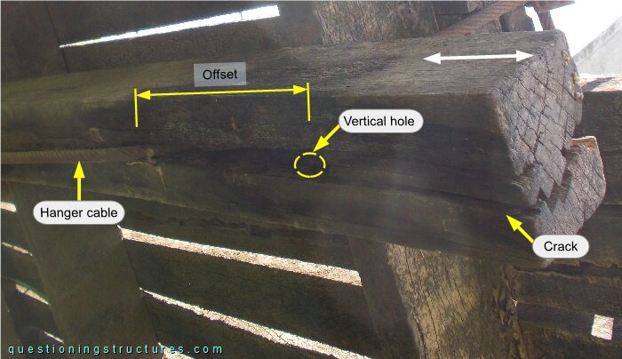
There is an offset between the vertical hole and the hanger's bent region, and a longitudinal crack (over the whole height) extends from the hanger's bent region until the end of the girder. The timber fiber direction is parallel to the length of the girder. A further connection viewed from the side is shown in figure 4.
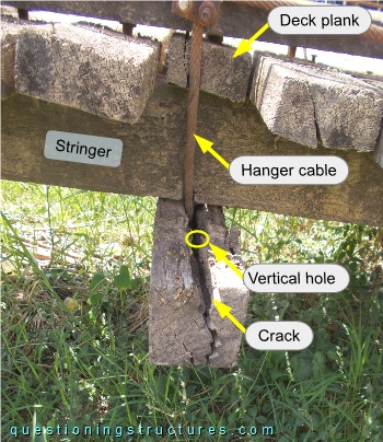
A similar crack configuration and hanger cable offset are noticeable; the hanger cable touches the stringer and a deck plank.
What are the main consequences?
Figure 5 shows a further hanger cable to girder connection.
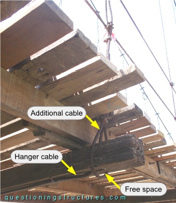
An additional cable is connected to the hanger cable (over the deck region) by U-bolt clamps, bent (approx. 180 degrees) around the girder, and fixed with two U-bolt clamps. Free space between the additional cable and the girder is noticeable.
Hanger Cables
Figure 6 shows a main span sector.
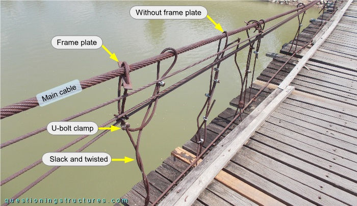
Noticeable are taut, slack, and twisted hanger cables, irregular spacing, different numbers of U-bolt clamps, and different main cable connections (e.g., with and without a frame plate).
Deck Deformation
Figure 7 shows a main span sector.
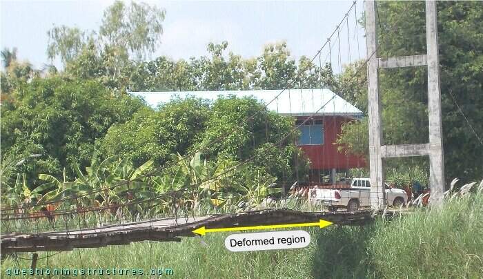
Deck deformation is noticeable.