General Information
Figure 1 shows a suspension bridge that is used by motorcycles, bicycles and pedestrians.
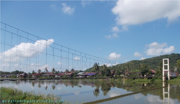
| Type | Single-span suspension bridge |
| Main span | ≅ 125 m |
| Deck width | ≅ 2 m |
| Deck width to main span ratio | ≅ 1:62 |
| Pylon | Reinforced concrete |
| Girder | Timber transverse beam |
Main Cables
Figure 2 shows the main cables in the bridge entrance region on one shore.
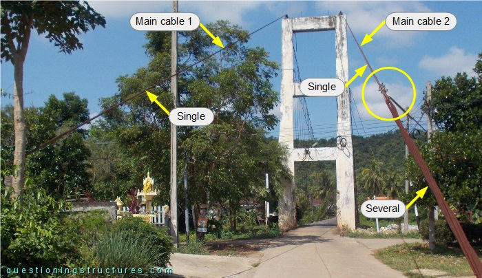
Main cable 1 is made of a single steel wire rope, while main cable 2 has a sector (from the anchorage until the yellow circle) made of several steel wire ropes. Figure 3 shows the connection between the single and the several wire ropes.
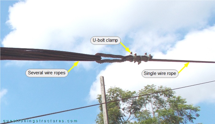
The wire ropes are directly connected (cable-to-cable connection), and the termination of the single wire rope consists of three U-bolt clamps: two U-parts are on the live end, while one U-part is on the dead end.
What are the main problems of the above shown connection?
Figure 4 shows main cable 2 viewed from the back.
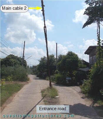
Main cable 2 is placed in the mid-region of the bridge entrance road without any protective structure.
Sag to Main Span Ratio
Figure 5 shows a side view of the main span.
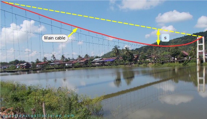
The sag s ≅ 3 m, and the main span is about 125 m; that gives a sag to main span ratio of approximately 1/42.