General Information
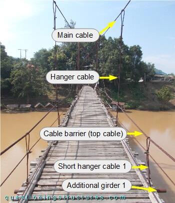
Figure 1 shows a suspension bridge that is used by motorcycles, bicycles and pedestrians.
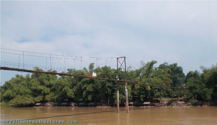
| Type | Two-span suspension bridge |
| Main span | ≅ 60 m |
| Deck width | ≅ 2 m |
| Deck width to main span ratio | ≅ 1:30 |
| Shore Pylon | Reinforced concrete |
| Central Pylon | Steel and reinforced concrete |
| Girder | Steel transverse beam |
Cross-Section
Figure 2 shows a schematic cross-section of the bridge.
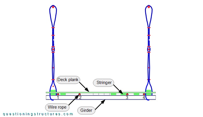
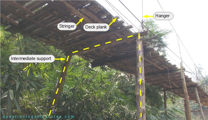
The girders are made of circular hollow sections, over which are placed timber stringers and four shore-anchored wire ropes (1 to 4). The stringers have an asymmetric and non-constant layout, and the timber deck planks are nailed over them. Figure 3 shows a bottom view of a bridge sector.
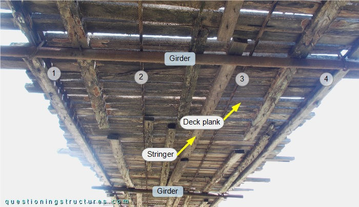
What are some possible reasons for an asymmetric and non-constant stringer layout?
Intermediate Supports
Figure 4 shows a schematic lateral view of the bridge.
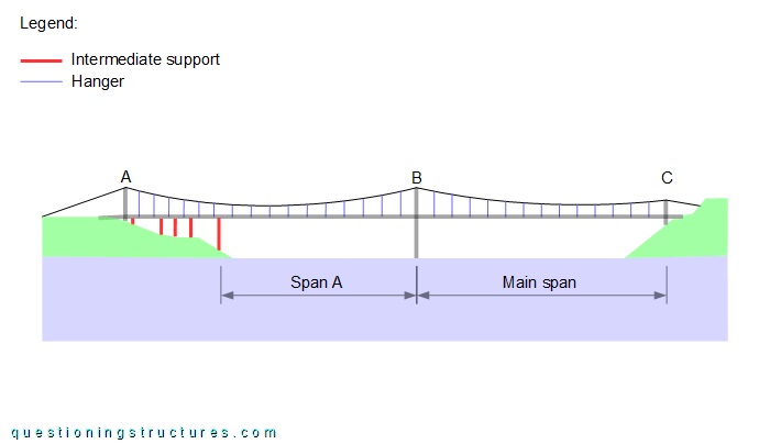
Between pylon A and the central pylon B are installed intermediate supports made of wood logs. The distance between pylons A and B ≅ 70 m, span A ≅ 47 m, the main span ≅ 60 m, and the hanger spacing is approximately constant. Figure 5 shows intermediate supports.
Wire Rope Bending
Figure 6 shows a hanger to main cable connection.
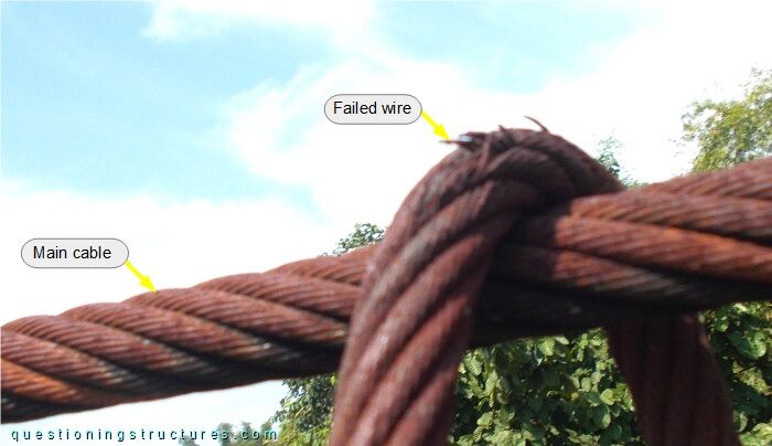
The hangers are made of steel wire ropes; they are bent over the main cables and terminated with U-bolt clamps. Enlarged view 1 is shown in figure 7.
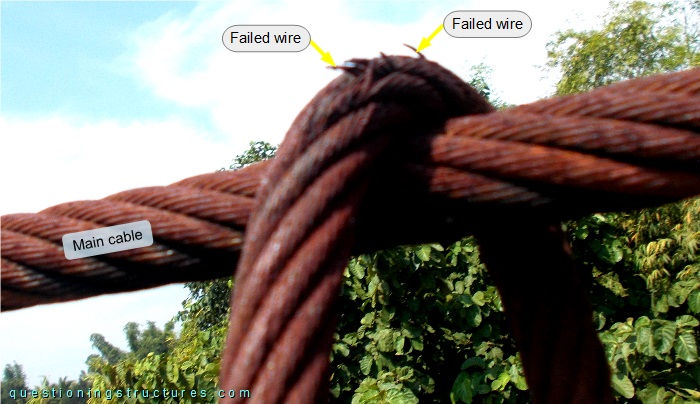
Failed wires at the outside bent region are noticeable.
What are the consequences?
Cable Barrier
Figure 8 shows a schematic lateral view of the central pylon (B) region.
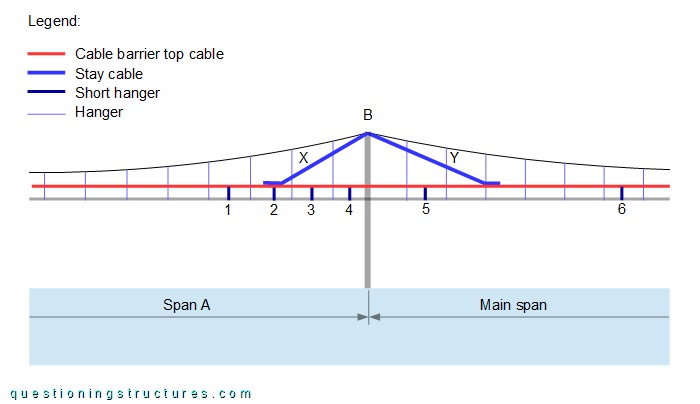
The cable barriers' top cables are anchored at the shores, and six additional girders (locations marked by the numbers) are connected to them by short hangers. Four stay cables (X and Y) are anchored at the cable barriers' top cables and at the pylon's top end. Figure 9 shows the anchorage at the cable barriers of the Y-stay cables.
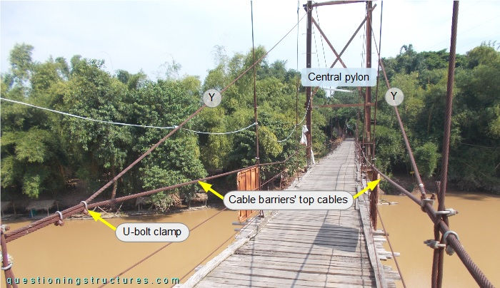
The anchorage consists of a direct (cable-to-cable) connection fixed with U-bolt clamps.
Figure 10 shows the main span in the central pylon region.
Single-Span Suspension Bridge
Figure 11 shows a schematic lateral view of the bridge and a single-span suspension bridge variant.
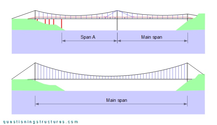
The main span of the single-span suspension bridge ≅130 m, the hanger spacing and the deck width ≅ 2 m, and the sag-to-main span ratio ≅ 1:10.
What is a possible cross-section of the single-span suspension bridge?`