General Information
Figure 1 shows a pedestrian suspension bridge.
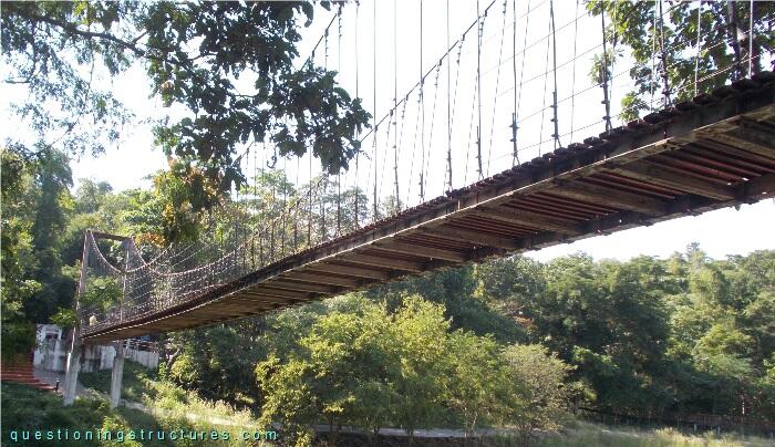
| Type | Three-span suspension bridge |
| Main span | ≅ 45 m |
| Deck width | ≅ 1.5 m |
| Deck width to main span ratio | ≅ 1:30 |
| Pylon | Steel and reinforced concrete |
| Girder | Steel longitudinal beam |
Connection Between Girder and Pylon
Figure 2 shows the girder in the pylon region.
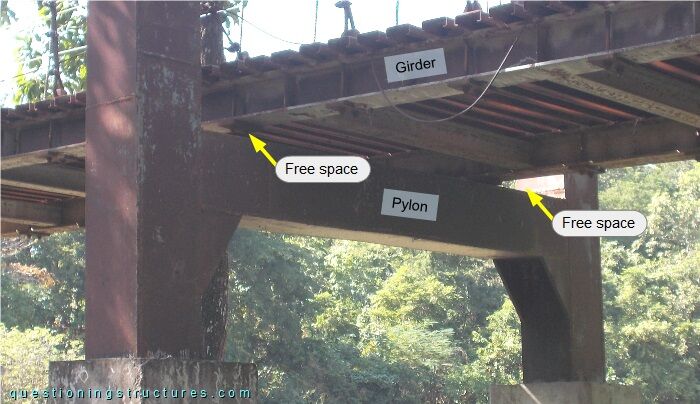
The girder is not connected to the pylon.
What are the main structural consequences?
Connection Between Girder and Abutment
Figures 3 and 4 show the girder in the abutment region.
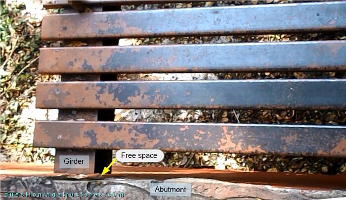
The girder is not connected to the abutment.
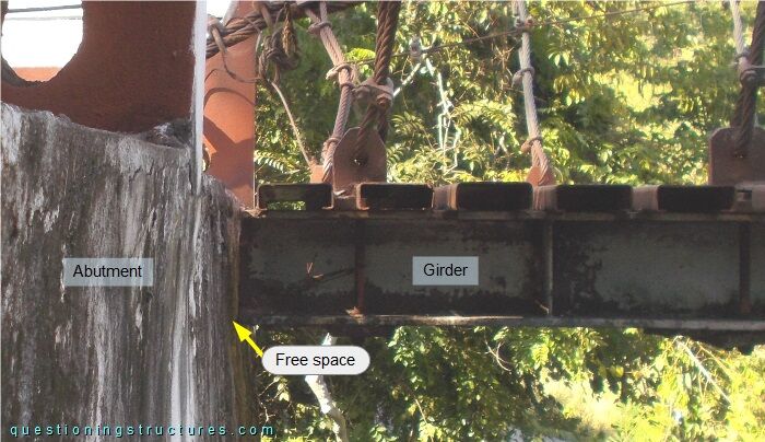
What are the main structural consequences?
Wire Rope Termination
Figure 5 shows two hangers at their bottom ends.
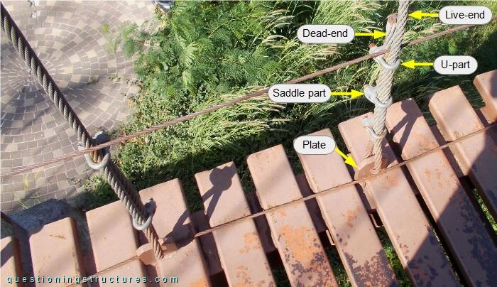
The hangers are made of steel wire ropes, and the end termination consists of U-bolt clamps. The U-parts are on the live end of the cables, and the wire ropes are connected directly (without wire rope thimbles) to the single-hole plates. The left hanger has two U-bolt clamps, while the right hanger has three U-bolt clamps.