General Information
Figure 1 shows a suspension bridge that is used by motorcycles, bicycles and pedestrians.
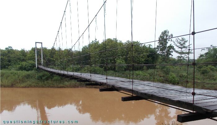
| Type | Single-span suspension bridge |
| Main span | ≅ 110 m |
| Deck width | ≅ 1.5 m |
| Deck width to main span ratio | ≅ 1:73 |
| Pylon | Reinforced concrete |
| Girder | Timber transverse beam |
Hanger Cable Deviation
Figure 2 shows a hanger.
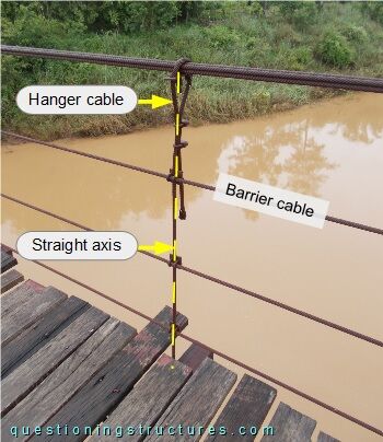
The hangers are also connected to the barrier cables by U-bolt clamps and frame plates. Figures 3 and 4 show two further hangers.
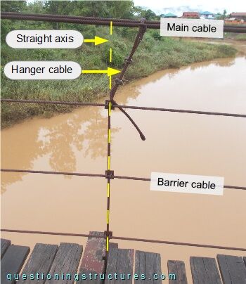
Hanger deviation between the main cable and cable barrier 1 is noticeable.
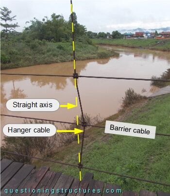
Hanger deviation between cable barriers 1 and 3 is noticeable.
What are the main consequences?
Cross-Section
Figure 5 shows a schematic cross-section of the bridge.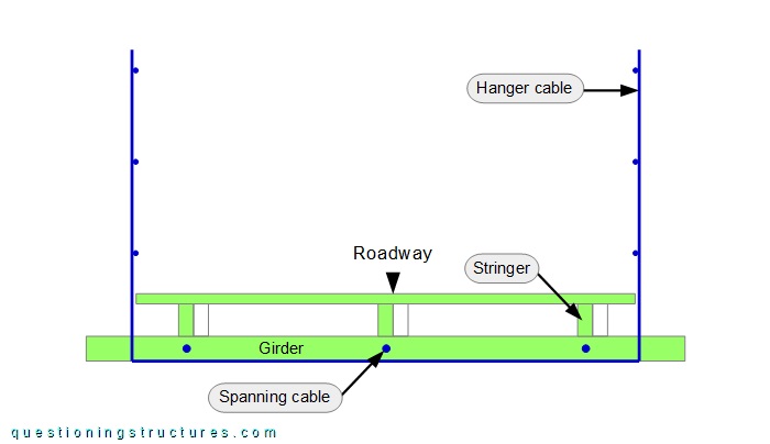
Each girder has three circular holes through which a steel wire rope passes; the wire ropes run over the whole span and are anchored at the pylons. A single hanger is used to connect the girder's bottom side by direct (cable-to-girder) contact, and the hanger termination consists of U-bolt clamps. The stringers and the deck are made of timber. Figure 6 shows a bottom view of the bridge.
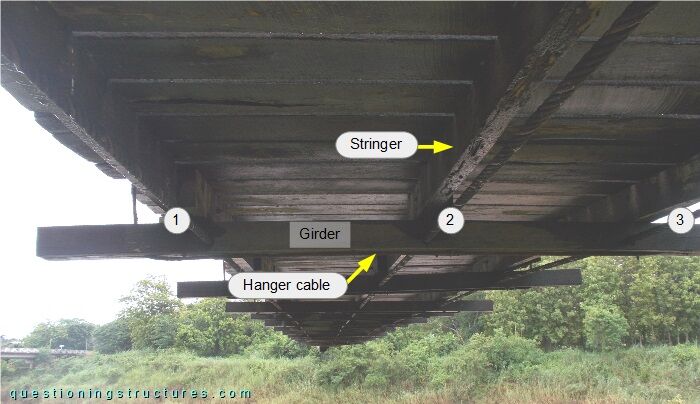
The wire ropes are indicated by the numbers.
Torsional Vibration of the Deck
Figure 7 shows a schematic lateral view of the bridge.
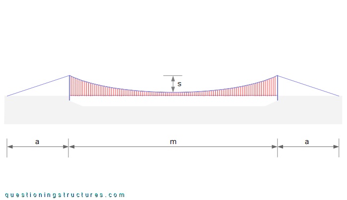
The hanger spacing ≅ 1 m, the length of the shortest hanger (mid-span) ≅ 1.5 m, the sag-to-main span ratio (s/m) ≅ 1:12, and the distance a (pylon-to-anchorage) ≅ 35 m. Video 1 shows the torsional vibration of the deck during single pedestrian-induced excitation in the mid-span region.