General Information
Figure 1 shows a suspension bridge that is used by motorcycles, bicycles and pedestrians.
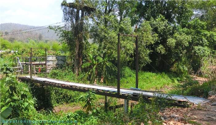
| Type | Single-span self-anchored suspension bridge |
| Main span | ≅ 9 m |
| Deck width | ≅ 1.5 m |
| Deck width to main span ratio | ≅ 1:6 |
| Pylon | Reinforced concrete and steel |
| Girder | Steel longitudinal beam |
Bridge Configuration
Figure 2 shows a schematic lateral view of the bridge.
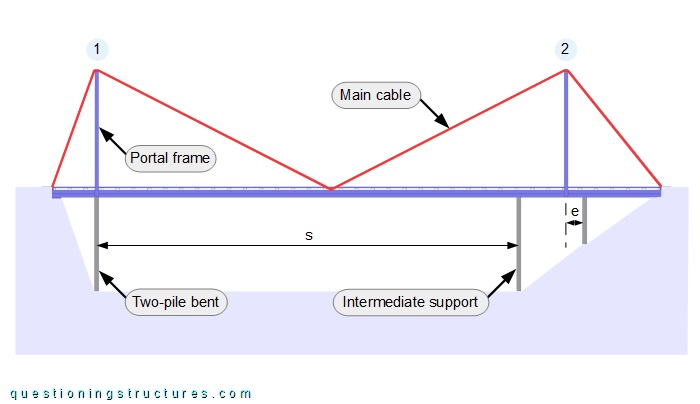
There are two pylons (1 and 2) and one intermediate support. A pylon consists of a two-pile (RC) bent and a steel portal frame; the intermediate support consists of a two-pile (RC) bent. There is an eccentricity (e) between the two-pile bent and the portal frame of pylon 2; e ≅ 0.4 m, and the main span s ≅ 9 m. The hanger-less main cables are made of steel wire ropes, are anchored at the girders' ends, and are connected to the top ends of the pylons and the mid-span region. Figure 3 shows a bottom view of the bridge.
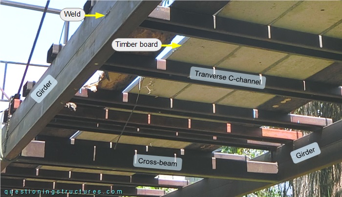
The girder consists of two rectangular hollow sections placed one on top of the other and joined by intermittent welding. The cross-beams are made of C-channels, and the deck consists of transverse C-channels and longitudinal timber boards. Figure 4 shows the connection between the main cable and the mid-span region.
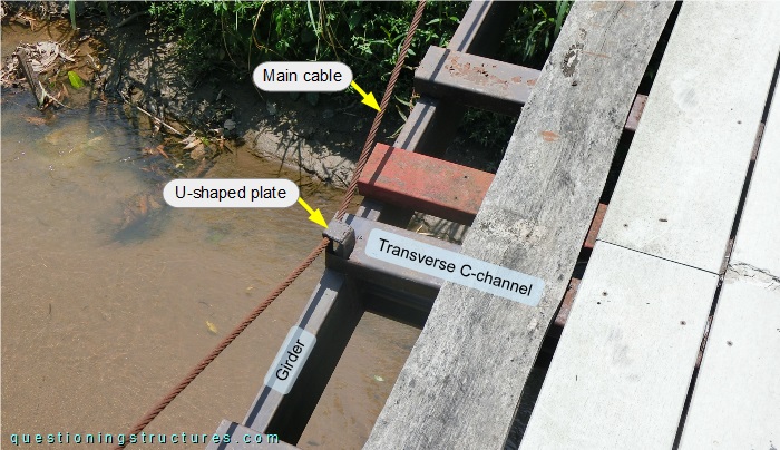
The main cable passes through a U-shaped plate that is welded to a transverse C-channel and the girder. Figure 5 shows a schematic three-dimensional view of the bridge.
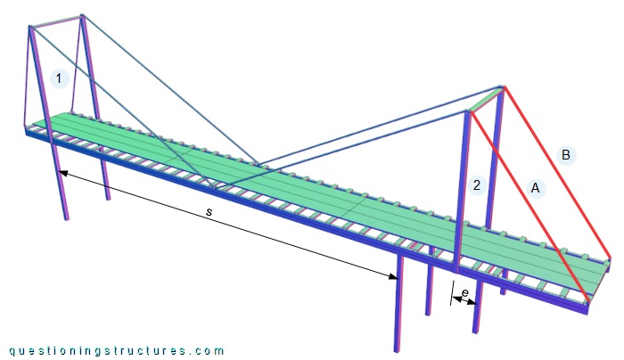
Video 1 shows the vibration of main cables A and B during hand-induced excitation.
Different Bridge Configurations
Figure 6 shows three schematic lateral views.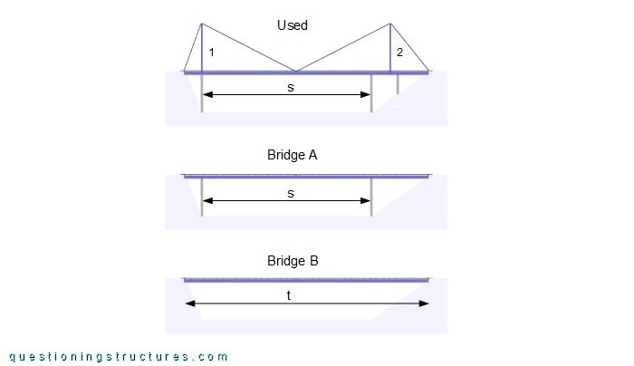
Bridge A is the used bridge without the main cables, pylon 2, and the portal frame of pylon 1; bridge B is bridge A without the two-pile bents. The span s ≅ 9 m, and the span t ≅ 13 m.