General Information
Figure 1 shows a suspension bridge that is used by motorcycles, bicycles and pedestrians.
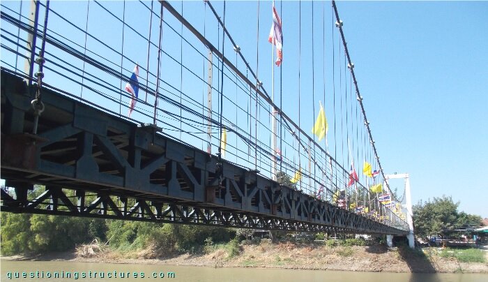
| Type | Single-span suspension bridge |
| Main span | ≅ 75 m |
| Deck width | ≅ 2 m |
| Deck width to main span ratio | ≅ 1:36 |
| Pylon | Reinforced concrete |
| Girder | Steel truss |
Hangers and their Connections
Figure 2 shows a schematic lateral view of the bridge.
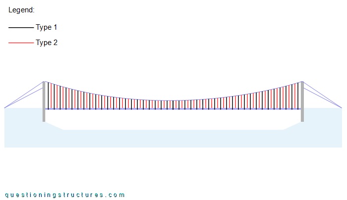
There are two hanger types: type 1 is made of a steel wire rope (black lines), while type 2 is made of a steel rod (red lines); they are alternately arranged, and the spacing is approximately 0.8 m. The connections to the main cable and to the girder are shown in figures 3 and 4, respectively.
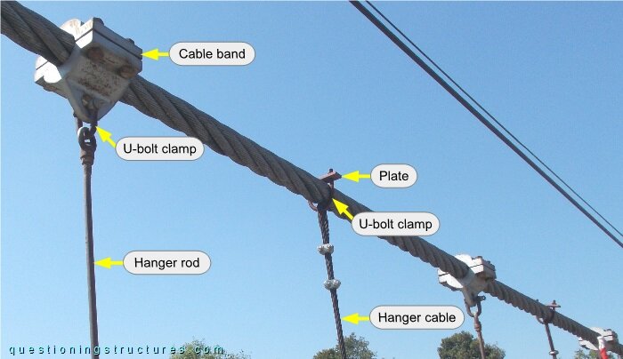
Type 1 is connected to the main cable by a U-bolt and a two-hole frame plate placed over the main cable, and the hanger termination consists of U-bolt clamps; type 2 has a ring termination and is connected to the main cable by a shackle and a cable band. The wire rope and the rod have approximately the same diameter.
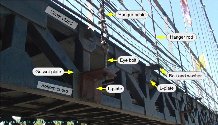
Type 1 is connected to the gusset plate of the bottom node by an eye bolt and an angle plate; type 2 is connected to the gusset plate of the upper node by an angle plate and a washer and bolt.
What are some possible reasons to use two different hanger types and connect them to the girder at different elevations?
Pylons' Backstay Cables
Figure 5 shows a front view of a pylon.
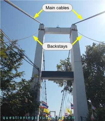
Besides the main cables, each pylon is connected to two sagging backstay cables made of steel wire ropes. The anchorage to the pylon is shown in figure 6.
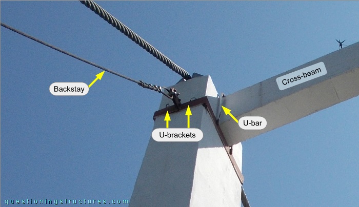
The backstays are terminated with U-bolt clamps, and the anchorage consists of two U-brackets and a U-bar; the latter is placed over the cross-beam and welded to a U-bracket. Figure 7 shows the opposite anchorage.
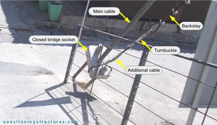
The backstay is connected to the same bridge socket used for the main cable anchorage by a turnbuckle and an additional wire rope; the latter is bent around the socket and terminated with U-bolt clamps.