General Information
Figure 1 shows a pedestrian suspension bridge.
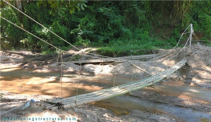
| Type | Single-span suspension bridge |
| Main span | ≅ 9 m |
| Deck width | ≅ 0.6 m |
| Deck width to main span ratio | ≅ 1:15 |
| Pylon | Tree trunk |
| Girder | Bamboo transverse beam |
Wooden Suspension Bridge Configuration
Figure 2 shows the pylon on shore 1.
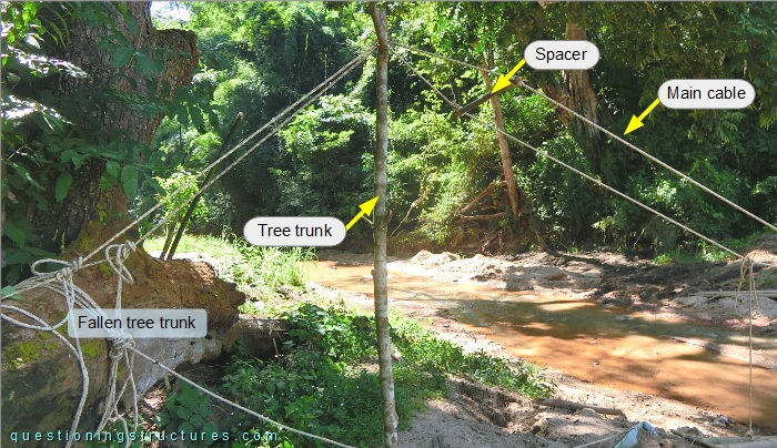
The pylon is made of a tree trunk, and the base is embedded in the ground. The main cables are made of ropes; they pass over the branch bark ridge and are anchored by tying to a fallen tree trunk. Bamboo poles are used as main cable spacers. Figure 3 shows the pylon on shore 2.
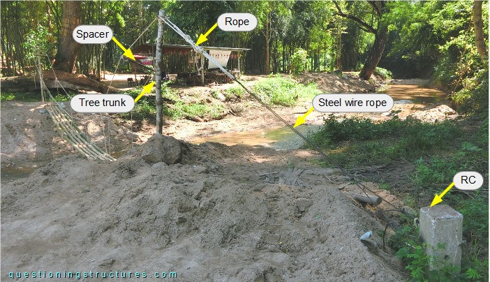
In contrast to shore 1, the main cables are anchored to a ground-embedded RC element by a single steel wire rope terminated with U-bolt clamps. Figure 4 shows the bridge entrance on shore 1.
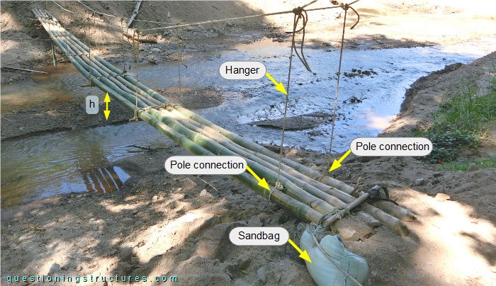
The abutment consists of a single sandbag, while the deck consists of five bamboo poles placed side-by-side and bundled by ropes. The hangers are also made of ropes, and the first hanger set is tied to the deck's external poles. The vertical clearance (h) is about 0.8 m. Figure 5 shows a main span sector.
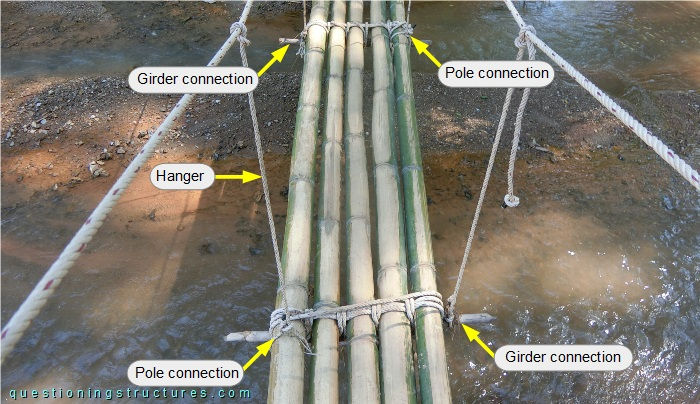
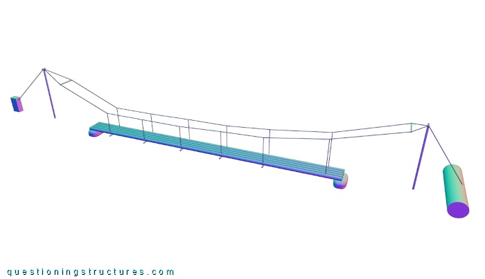
The hangers are tied to the girders and the deck's external poles. Figure 6 shows a schematic three-dimensional view of the bridge.
Different Bridge Configuration
Figure 7 shows a schematic three-dimensional view of the bridge and a two-span continuous beam bridge that uses sand bags for the intermediate support.
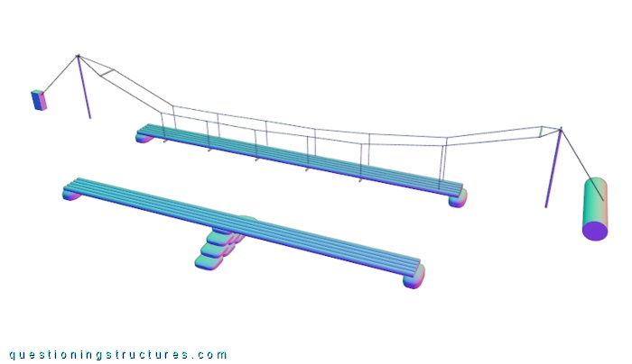
Which variant uses resources probably more efficiently?
What are the main problems of the suspension bridge and the beam bridge?