General Information
Figure 1 shows a suspension bridge that is used by motorcycles, bicycles and pedestrians.
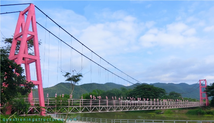
| Type | Single-span suspension bridge |
| Main span | ≅ 90 m |
| Deck width | ≅ 1.5 m |
| Deck width to main span ratio | ≅ 1:60 |
| Pylon | Reinforced concrete (A-type, longitudinal) |
| Girder | Steel truss |
Steel Truss Girder
Figure 2 shows a schematic three-dimensional view of a steel truss girder sector.
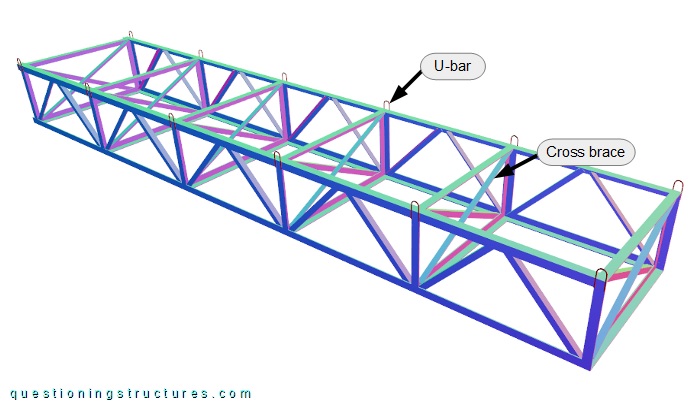
The truss is made of L-sections and consists of zig-zag diagonals, verticals, cross members, and cross braces. The verticals, the cross members, and the cross braces are placed each zig-zag period. The hangers are connected to the upper chords over the verticals by welded U-bars. Figure 3 shows the truss viewed from below.
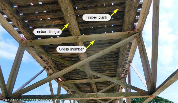
Over the cross members are placed three timber stringers, and the deck consists of timber planks.
Figure 4 shows a side view of a bridge sector on shore 1.
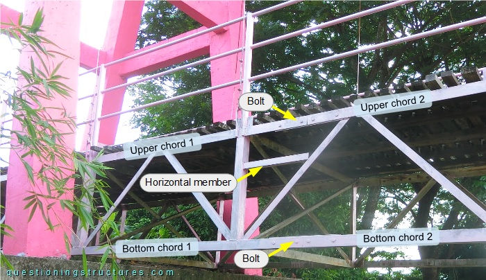
A horizontal member made of an L-section connects a vertical with a diagonal (on one side and shore 1 only). The same region is used for the chord-to-chord connection, which consists of an additional (overlapping) L-section fixed by bolts and nuts.
Figure 5 shows a side view of a bridge sector on shore 2.
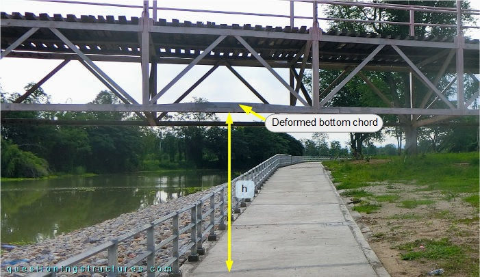
A deformed bottom chord is noticeable, and the vertical clearance h ≅ 2 m. Figure 6 shows the deformed bottom chord.
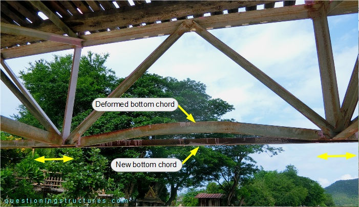
A new bottom chord made of an L-section with a smaller size is welded to the bottom node regions.
How does the new bottom chord affect the stiffness of the truss?