General Information
Figure 1 shows a pedestrian suspension bridge.
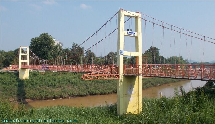
| Type | Three-span suspension bridge |
| Main span | ≅ 60 m |
| Deck width | ≅ 1.5 m |
| Deck width to main span ratio | ≅ 1:40 |
| Pylon | Reinforced concrete with two steel cantilever lateral trusses |
| Girder | Steel half-through truss |
Lateral Cables and Main Span Range
Figure 2 shows a schematic three-dimensional view of the bridge.
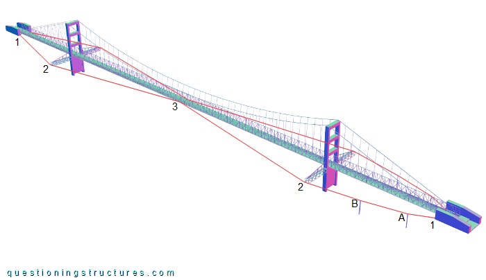
There are two lateral cables; they are connected to the anchorages (1), the steel columns (A and B), the free ends of the cantilever lateral trusses (2), and the girder in the main span mid-span region (3). The steel columns are only installed on shore 1. Figure 3 shows a lateral cable between the anchorage (1) and the cantilever lateral truss (2) on shore 1.
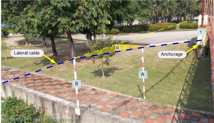
The columns are made of circular hollow sections. Column A is based on the ground, while column B is based on the top of a reinforced concrete yard wall. The lateral cable is horizontally deviated (angle α) on column B. Figure 4 shows a column to lateral cable connection.
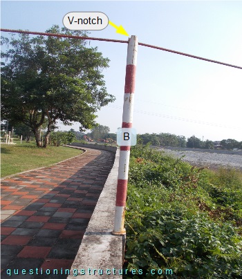
The top end of the column has a V-notch, and the lateral cable passes through it. Figure 5 shows a lateral cable between the cantilever lateral truss and the main span mid-span region viewed from shore 1.
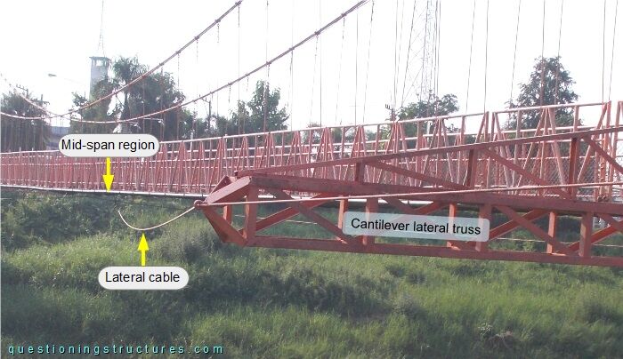
The lateral cable is sagging.
How efficient are the above shown lateral cables?
Main Cable Anchorage
The main cables are connected to the front side of the anchor blocks (on shores 1 and 2) as shown in figure 6.
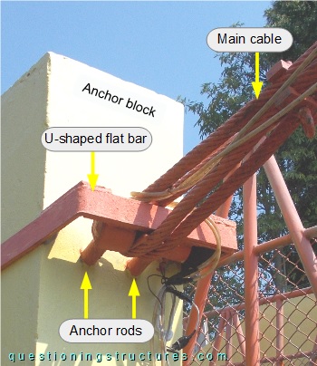
The connection consists of two embedded anchor rods (joined by a pin) and a U-shaped flat bar, which is terminated as shown in figures 7 and 8.
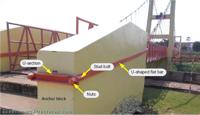
On shore 1, the U-shaped flat bar is terminated with two welded stud bolts, a U-section, and four nuts.
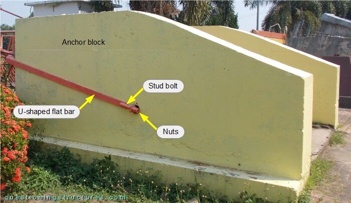
The U-shaped flat bar has the same termination as shore 1, but the U-section passes through the anchor block instead of connecting its back side.
What is the purpose of the U-shaped flat bars?