General Information
Figure 1 shows a pedestrian suspension bridge.
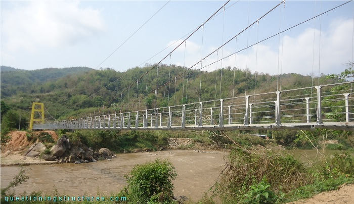
| Type | Single-span suspension bridge |
| Main span | ≅ 80 m |
| Deck width | ≅ 1.5 m |
| Deck width to main span ratio | ≅ 1:53 |
| Pylon | Reinforced concrete |
| Girder | Steel transverse beam |
Anchorage
Figure 2 shows an anchorage.
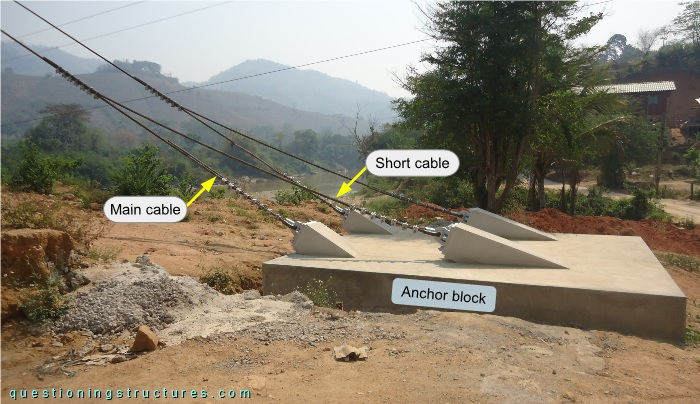
The main cables are connected to the front region of the anchor block, and the short cables are connected to the mid-region of the anchor block. The main and the short cables are of the same type and size and are connected as shown in figure 3.
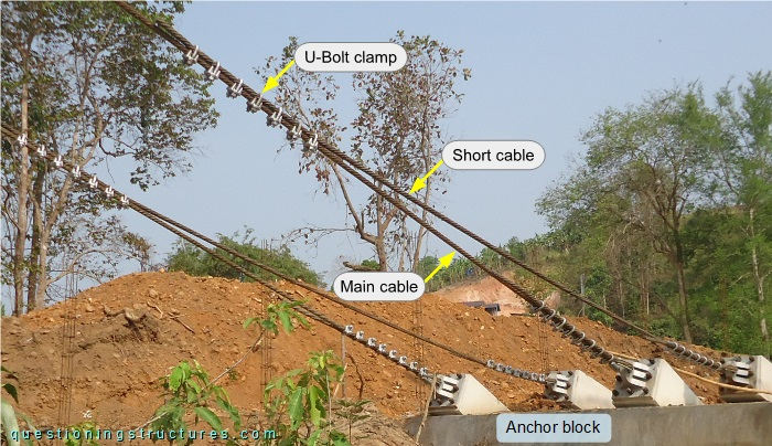
The two cables are overlapped and fixed with U-bolt clamps. Figure 4 shows a schematic lateral view of an anchorage.
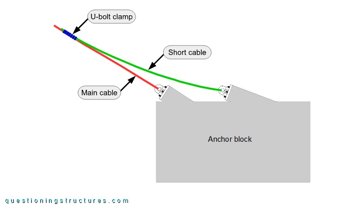
The short cables are sagging.
Bottom Cables
Figure 5 shows the main span.
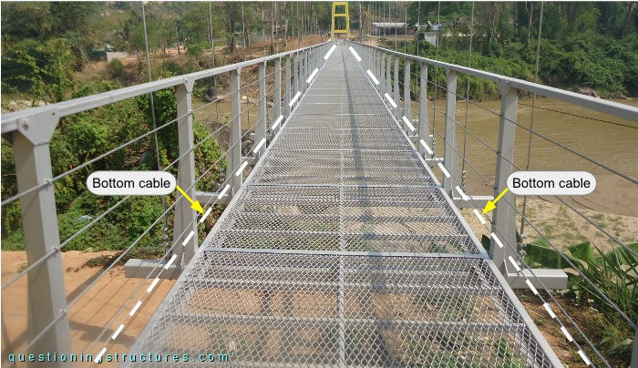
There are two bottom cables; they run over the girders and are anchored to the pylons. Figure 6 shows a bottom cable.
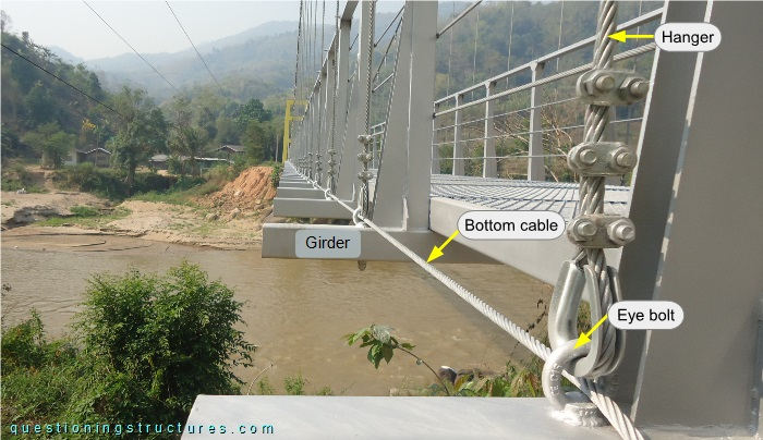
The bottom cable passes through the holes of the eye bolts used for the hanger-to-girder connection. The pylon anchorage is shown in figure 7.
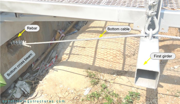
The bottom cable is vertically and horizontally deviated at the first girder and connected to horizontal rebars of the pylon's bottom cross beam. The bottom cable termination consists of a cable thimble and U-bolt clamps.