General Information
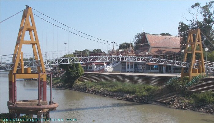
Figure 1 shows a pedestrian suspension bridge.
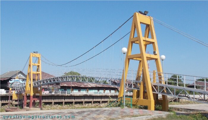
| Type | Single-span suspension bridge |
| Main span | ≅ 30 m |
| Deck width | ≅ 1 m |
| Deck width to main span ratio | ≅ 1:30 |
| Pylon | Reinforced concrete (A-type, longitudinal) |
| Girder | Curved steel truss |
Pylons
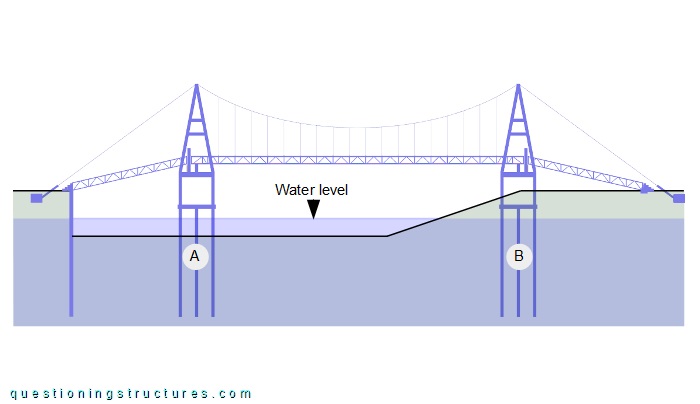
Figure 2 shows a side view of the bridge.
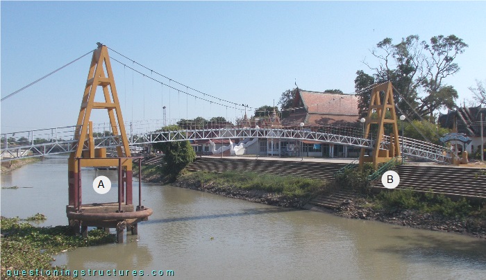
Pylon A is placed in the river, while pylon B is placed in the river embankment. Figure 3 shows a schematic longitudinal section of the bridge.
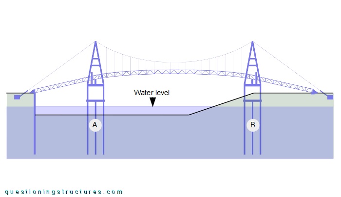
The foundation of each pylon consists of a pile cap and piles.
Connection Between Main Span Truss and Pylons
Figure 4 shows the connection between the main span truss and the pylon.
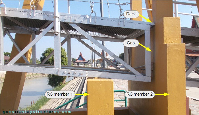
The truss is made of L-sections; the bottom chords are connected without any fastening to RC member 1, which is placed away from the nodes. Truss and RC member 2 are separated by a gap, while deck and RC member 2 are joining.
What type of support can be used for modeling the truss to pylon connection?
Curved Truss
Figure 5 shows a side view of the main span.
The truss of the main span has a slight curvature. Suppose to replace the curved truss with a horizontal truss with the same height and width, members (type and size), and connection to the pylons as the curved truss, as shown in the schematic longitudinal section in figure 6.
Main Cables
A main cable consists of three side-by-side placed steel wire ropes, as shown in figure 7.
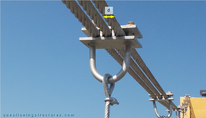
A wire rope has a diameter (d) of approximately 30 mm. Figure 8 shows a roadway view of the bridge.
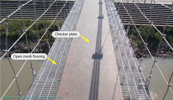
The deck consists of open mesh flooring with checker plates. Assume a dead load (deck + truss) of 150 kg/m2 and a live load of 400 kg/m2.
Main Cables Anchorage
Figure 9 shows a main cable anchorage.
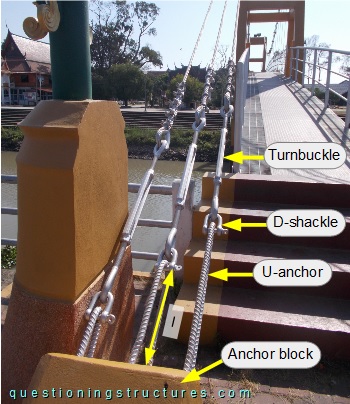
The main cable is connected to the anchor block by turnbuckles, D-shackles, and U-anchors, which have different non-embedded lengths (l).
Span Range and Bridge Type
Figure 10 shows a schematic longitudinal section of the bridge.
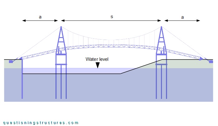 An approach span (a) ≅ 10 m, the main span (s) ≅ 30 m, and the deck width ≅ 1 m. An approach span consists of a truss bridge made of L-sections with the same sizes as the main span girder.
What are other possible bridge types that probably use fewer resources for those span ranges?