General Information
Figure 1 shows a suspension bridge that is used by vehicles up to 1.5 tons, bicycles and pedestrians.
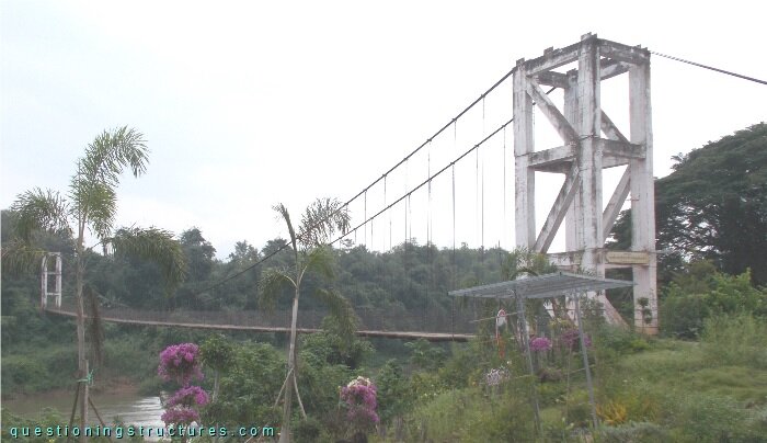
| Type | Single-span suspension bridge |
| Main span | ≅ 140 m |
| Deck width | ≅ 2.5 m |
| Deck width to main span ratio | ≅ 1:56 |
| Pylon | Reinforced concrete |
| Girder | Steel transverse beam |
Pylons
Figure 2 shows a pylon.
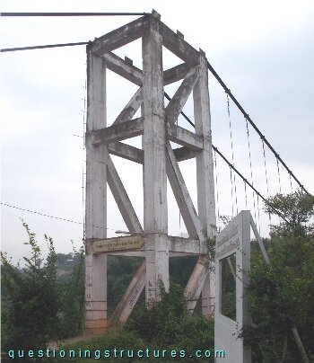
The pylon consists of a reinforced concrete truss tower. Figure 3 shows a schematic three-dimensional view of the pylon and a portal-type pylon with saddles.
| Used pylon | Portal-type with saddles |
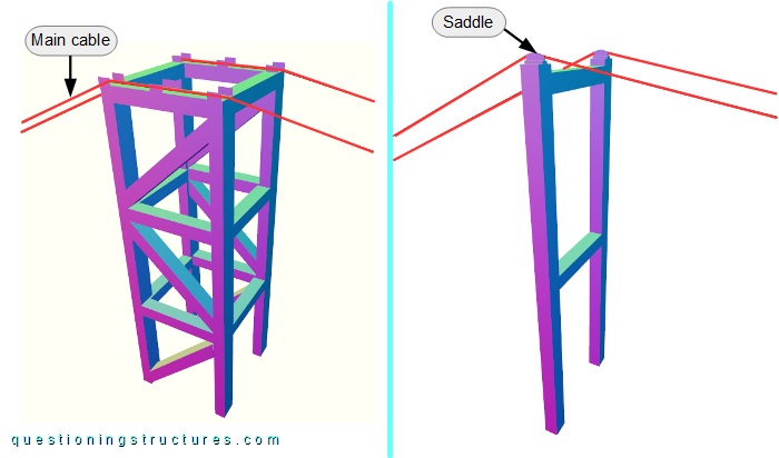
Is the used pylon required for efficiency reasons?
Hanger Cable to Girder Connection Failure
Figure 4 shows a schematic cross-section of the bridge.
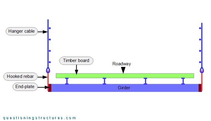
The girder is made of two side-by-side placed U-sections, the stringers are made of I-sections, and the deck is made of timber planks. The connection between the hanger cable and the girder consists of a rebar and an end-plate. Figure 5 shows a hanger cable to girder connection.
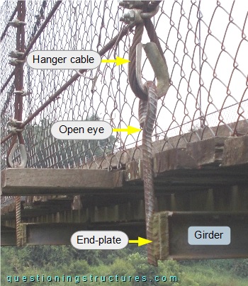
The rebar has an open eye end; the girder, the end-plate, and the rebar are joined by welding. Figure 6 shows a failed rebar.
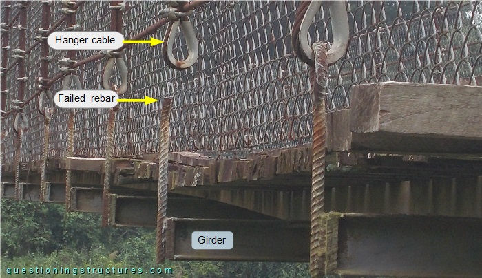
The failure is located at the start of the bent region.
Does this failure affect the safety of the bridge?