General Information
Figure 1 shows a pedestrian suspension bridge.
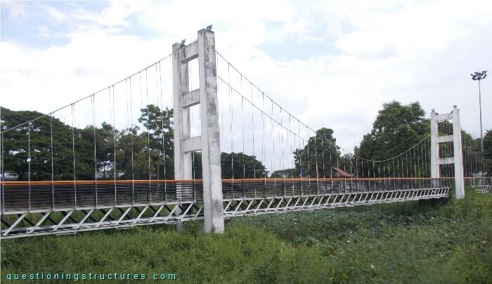
| Type | Three-span suspension bridge |
| Main span | ≅ 40 m |
| Deck width | ≅ 1.5 m |
| Deck width to main span ratio | ≅ 1:27 |
| Pylon | Reinforced concrete |
| Girder | Steel truss |
Truss Configuration
Figure 2 shows a side view of a truss girder sector.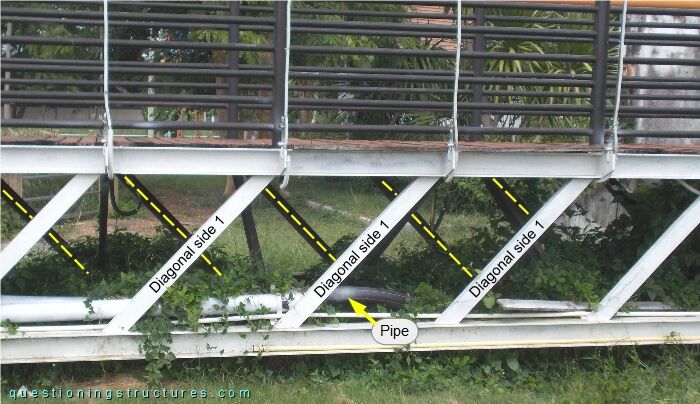
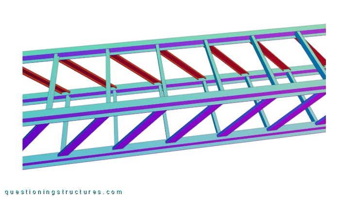
The truss does not have verticals, and the diagonals of side 1 are sloping in the opposite direction to the diagonals of side 2 (yellow dashed lines). The truss girder also carries two pipes; the upper and bottom chords are made of H-sections, while the remaining truss members are made of U-sections. Figure 3 shows a schematic three-dimensional view of a truss girder sector.
Pylons
Figure 4 shows a pylon viewed from the front, while figure 5 shows an enlarged view of its top-end region.
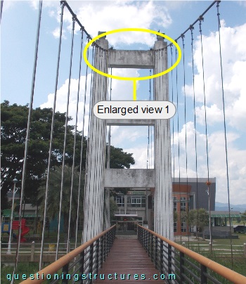
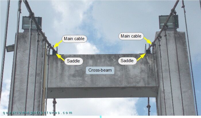
The the saddles are placed over the cross-beam.
What are the main structural consequences?
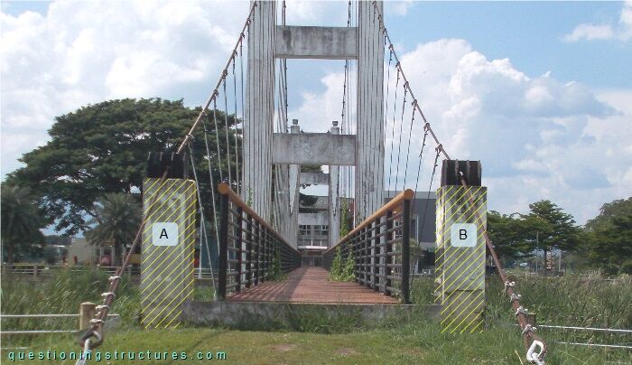
Bridge Entrance
The bridge entrance has two reinforced concrete columns (A and B) per shore, as shown in figure 6.
Steel plates are installed on the top of each column, as shown in figure 7.
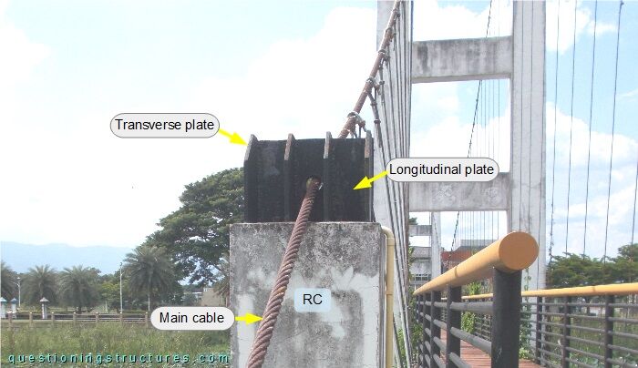
There are nine vertically arranged plates: a longitudinal plate, which has a hole in the center, and eight transverse plates. The main cable passes through the hole of the longitudinal plate, and the plates are connected to the RC column by a base plate and anchor bolts.
Hanger Cable to Main Cable Connection
Figure 8 shows a hanger cable to main cable connection.
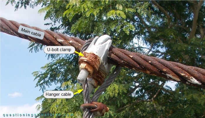
The hanger cable passes over the main cable, and the U-bolt clamp passes over the hanger cable.