General Information
Figure 1 shows a pedestrian suspension bridge.
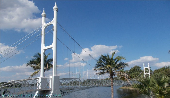
| Type | Single-span suspension bridge |
| Main span | ≅ 50 m |
| Deck width | ≅ 2 m |
| Deck width to main span ratio | ≅ 1:25 |
| Pylon | Reinforced concrete |
| Girder | Steel half-through truss |
Hanger Cables
There are three types of hanger cables, as shown in the schematic lateral view in figure 2.
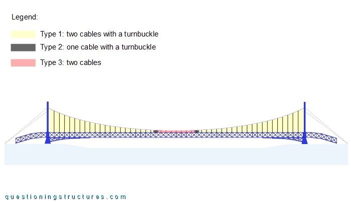
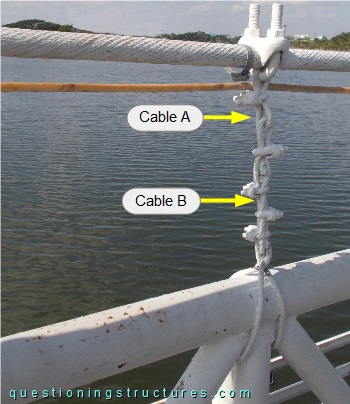
Type 1 consists of two cables with a turnbuckle, type 2 consists of one cable with a turnbuckle, and type 3 consists of two cables. Type 1 is installed from the main span beginning until the mid-span region, followed by type 2 (only two hangers per main cable); type 3 is installed in the remaining mid-span region. The cables are made of steel wire ropes. The three hanger types are shown in figures 3 to 5.
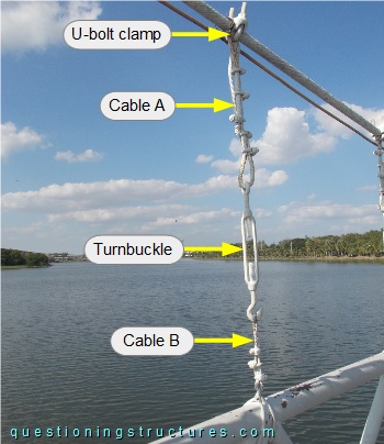
The turnbuckle, which is of type open body with eye and hooked ends, is connected to cables A and B; cable A is connected to the main cable by a U-bolt clamp, while cable B is looped around the upper node of the half- through truss. Cable A is terminated with five U-bolt clamps, while cable B is terminated with three U-bolt clamps.
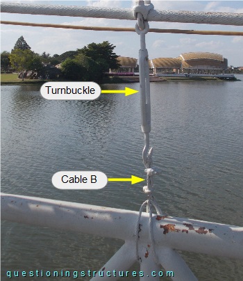
The turnbuckle is connected to the main cable (by a U-bolt clamp) and to cable B, which is looped around the upper node of the half-through truss and terminated with two U-bolt clamps.
Cable A is connected to the main cable (by a U-bolt clamp) and cable B, which is looped around the upper node of the half-through truss and terminated with four U-bolt clamps; cable A is terminated with one U-bolt clamp.
What is the purpose of the above shown hanger cable concept?
What are the main problems of the above shown hanger cables?
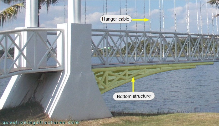
Girder in the Pylon Region
The bottom chords of the half-through truss in the pylon region are connected to a tapered truss made of circular hollow sections, as shown in figure 6.