General Information
Figure 1 shows a suspension bridge that is used by motorcycles, bicycles and pedestrians.
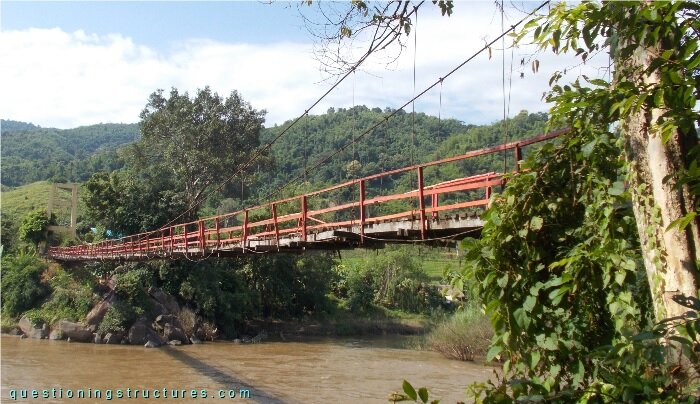
| Type | Single-span suspension bridge |
| Main span | ≅ 90 m |
| Deck width | ≅ 2 m |
| Deck width to main span ratio | ≅ 1:45 |
| Pylon | Reinforced concrete |
| Girder | Timber transverse beam |
Hanger Rods
The hangers are made of steel rods, as shown in figure 2.
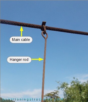
Figure 3 shows the top region of a hanger rod.
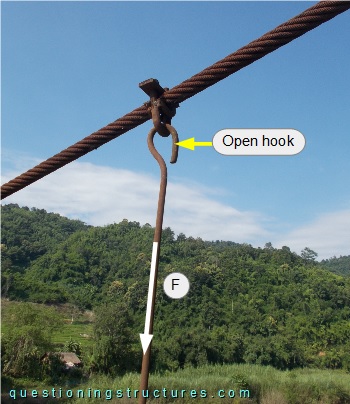
The rod top has an open hook, and the white arrow represents an axial force (F). Figure 4 shows a further hanger rod top.
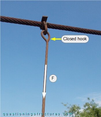
The rod top has a closed hook.
Hanger Rod to Timber Girder Connection
Figure 5 shows a schematic cross-section of the bridge.
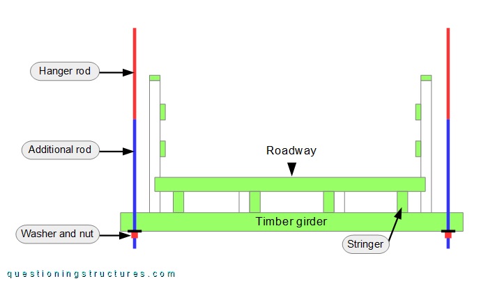
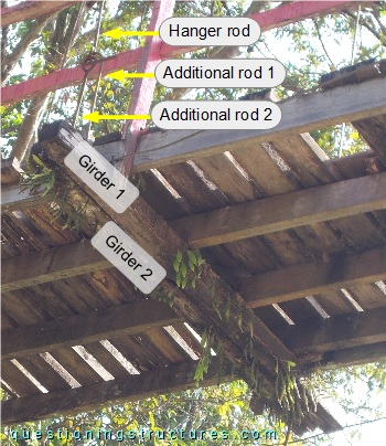
The connection between the hanger rod and the timber girder consists of an additional rod, a washer and a nut. Figure 6 shows a connection between a hanger rod and the girder viewed from above.
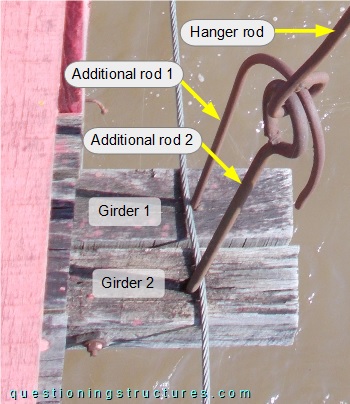
The girder is made of two side-by-side placed beams; they are each connected by an additional rod with a different shape.
Figure 7 shows a further connection.
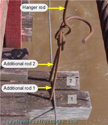
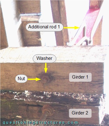
Figure 8 shows a connection viewed from below.
Timber Condition
Figure 9 shows a main span sector viewed from below.
Vegetation growing on the beams is noticeable.
Hanger Rod to Timber Girder Connection Failures
Figure 10 shows a main span sector viewed from below.
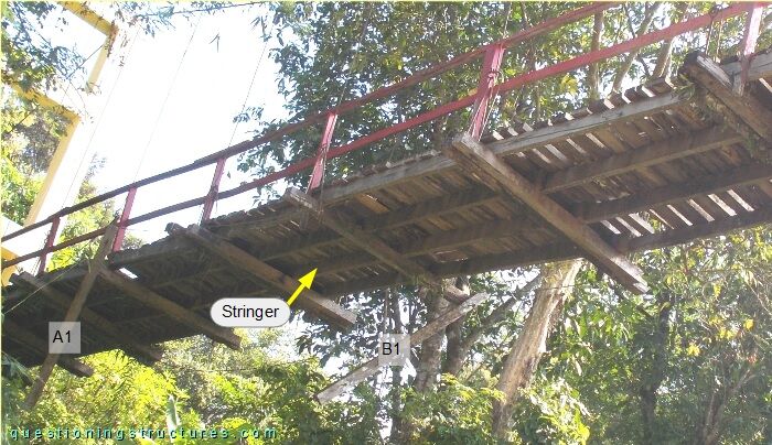
Due to the connection failures, beams A1 and B1 are not supporting the stringers.
Are those failures affecting the safety of the bridge?