General Information
Figure 1 shows a suspension bridge that is used by motorcycles, bicycles and pedestrians.
| Type | Single-span suspension bridge |
| Main span | ≅ 130 m |
| Deck width | ≅ 2 m |
| Deck width to main span ratio | ≅ 1:65 |
| Pylon | Reinforced concrete |
| Girder | Steel twin I-girder |
Wind Guy System
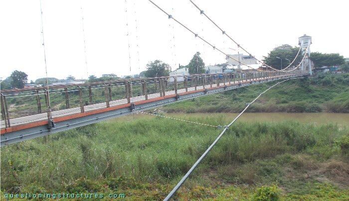
Figure 2 shows a side view of the main span.
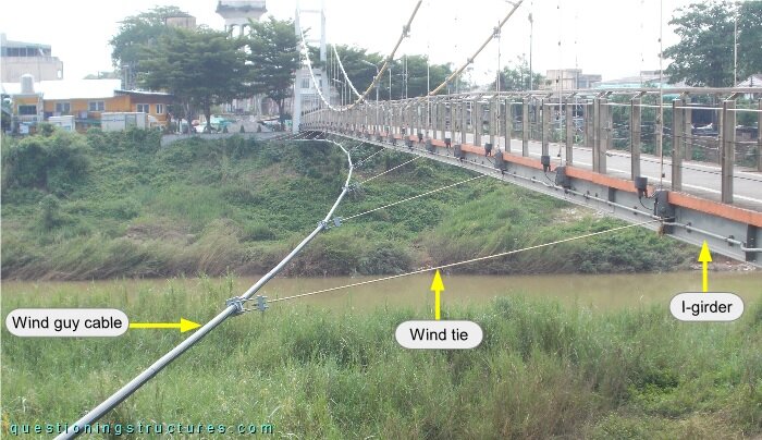
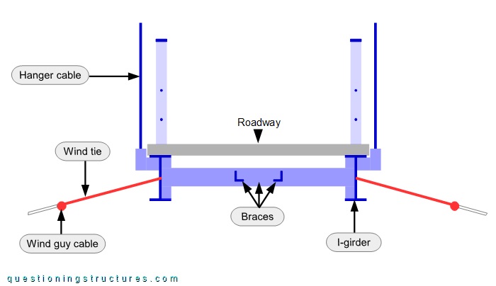
The shore-anchored wind guy cable is connected to the I-girder by the wind ties. There are a total of two wind guy cables (one per side) and 26 wind ties (13 per side). Figure 3 shows a schematic cross-section of the bridge.
Girder
Figure 4 shows a schematic three-dimensional view of the steel structure of the main span.
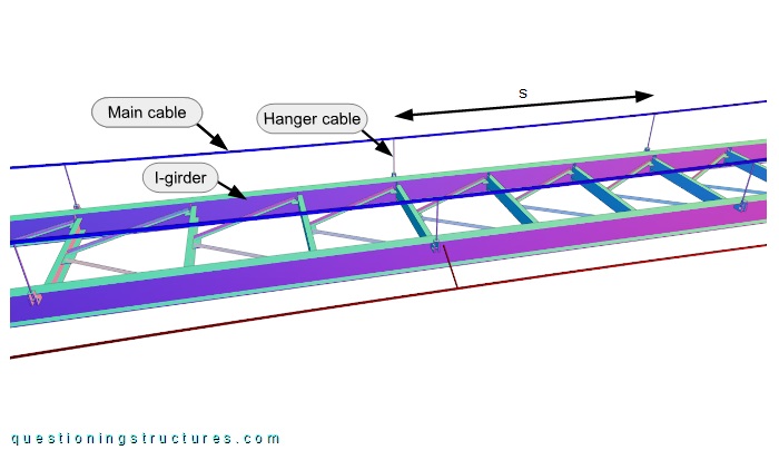
The girder layout is longitudinal, and the distance between the hanger cables s ≅ 4.5 m.
Girder-to-Girder Connection
Figure 5 shows a side view of a main span sector.
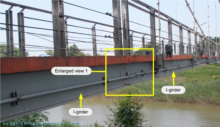
Enlarged view 1 is shown in figure 6.
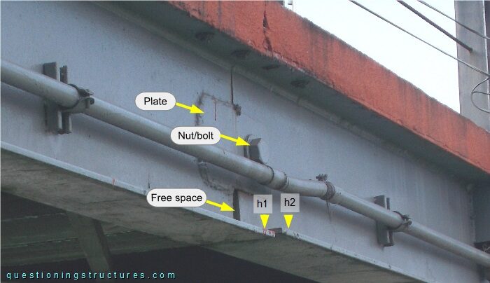
The girder-to-girder connection consists of two web plates and a bolt and nut, which are placed at the mid-height of the I-girder. The bottom flanges are at different elevations (h1 ≠ h2), and there is an increasing free space —top to bottom—between the webs.
What are some possible reasons for the different elevations of the bottom flanges?
Backstay Cables
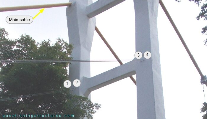
Figure 7 shows a pylon viewed from the front.
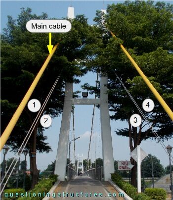
Besides the main cables, each pylon is connected to four backstay cables (marked by the numbers). Figure 8 shows a side view of the backstays to pylon connection region.