Traffic Light Pole
Figure 1 shows a mast arm structure.
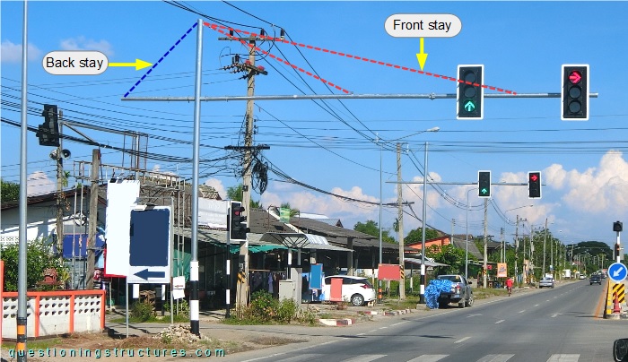
The structure is made of circular hollow sections and consists of a pole, a front mast, and a short back mast; the front mast is connected to two stay cables, while the back mast to one stay cable. Figure 2 shows the top region of the pole.
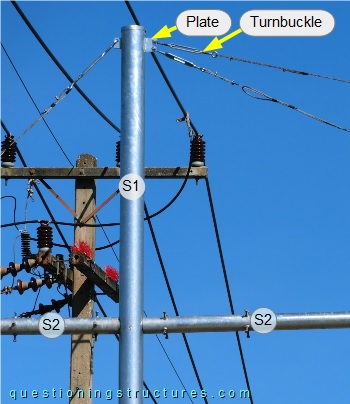
The stiffness of the pole (S1) is higher than the stiffness of the masts (S2). The stay cables are tensioned with turnbuckles, which are connected to the pole by plates. A schematic lateral view of the above shown structure and a variant without the back mast are shown in figure 3.
| With back mast | Without back mast |
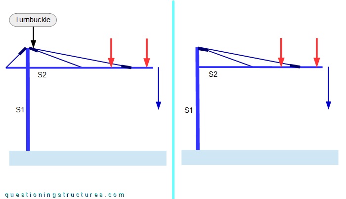
The red arrows represent forces, and the blue arrows indicate the vertical displacement direction of the free-ends. Assume that both structures (except for the back mast) and loads are equal .
What are some possible reasons to install the above shown stay cables?