Traffic Light Pole
Figure 1 shows a mast arm structure.
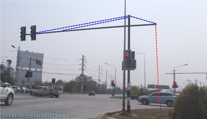
The structure is made of circular hollow sections and consists of a pole, a front mast, and a short back mast; the front mast is connected to two stay cables, while the back mast is connected to a stay- and a guy cable (red dashed line). Figure 2 shows the top region of the pole.
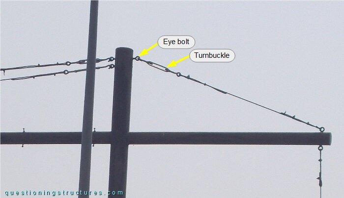
The stay cables are tensioned with turnbuckles, which are connected to the pole by eye bolts. Two schematic lateral views are shown in figure 3.
| Structure 1 | Structure 2 |
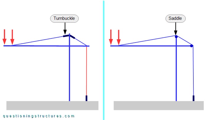
Structure 1 is the above shown light pole with a single front stay cable instead of two; there are a total of two stay cables, a guy cable, and three turnbuckles. Structure 2 has a single uninterrupted cable with one turnbuckle; the cable passes over two saddles. The red arrows represent forces. Assume that both structures and loads are equal, except for the previously mentioned.
What are some possible reasons for using structure 1 instead of structure 2?
Figure 4 shows a partial view of the structure and an enlarged view of it.
| Partial view | Enlarged view 1 |
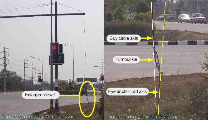
The guy cable is connected to an eye anchor rod by a turnbuckle; the guy cable axis is skew to the eye anchor rod axis.