General Information
Figure 1 shows a single post swing arm barrier.
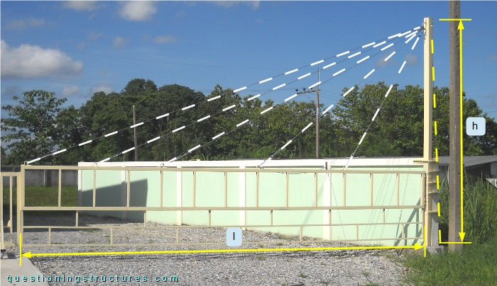
The post height h ≅ 3 m, and the arm length l ≅ 5 m. The structure has one back and five front stay cables (yellow and white dashed lines). The post and the arm are made of steel square hollow sections, while the stay cables are made of steel wire ropes.
Structural Concept
Figure 2 shows the barrier.
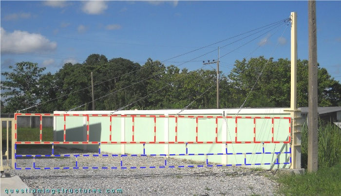
The arm has an external rectangular shape and an internal square and rectangular grid. Two sections are used for the arm: about 40 x 40 mm (red dashed lines) and 20 x 20 mm (blue dashed lines). The arm is connected to the post as shown in figure 3.
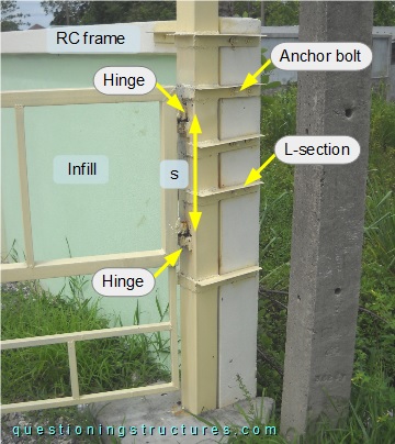
The connection consists of two hinges that are placed apart at a distance s ≅ 0.35 m. The post is connected to the RC column of the boundary wall frame by short L-sections and anchor bolts. The stay cables are connected to the arm as shown in figure 4.
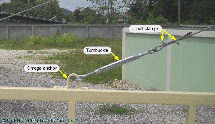
The connection consists of a turnbuckle and an omega anchor, and the wire rope termination consists of U-bolt clamps. Omega anchors are also used to connect the back and frontstays to the post, as shown in figure 5.
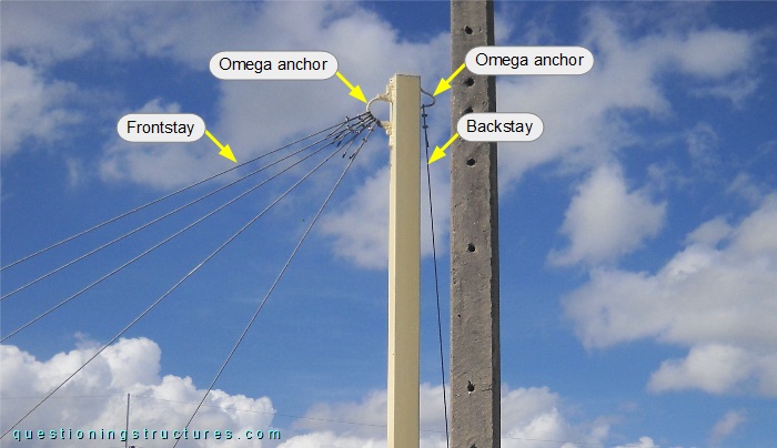
The backstay is connected to the RC column of the boundary wall frame, as shown in figure 6.
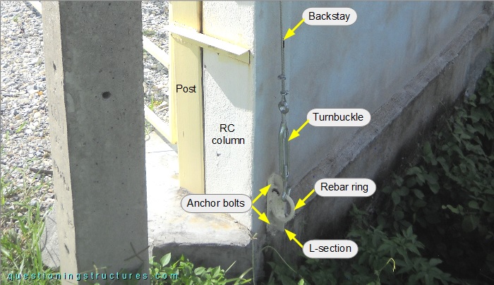
The connection consists of a turnbuckle, a rebar ring welded on a short L-section, and two anchor bolts. Figure 7 shows a schematic lateral view of the structure.
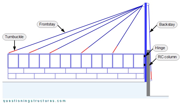
What are some possible structural optimization measures?