General Information
Figure 1 shows a truss bridge that is used by motorcycles, bicycles and pedestrians.
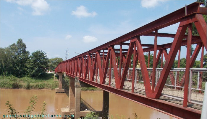
| Main span | ≅ 45 m |
| Type | Through-truss bridge |
| Truss material | Steel |
| Truss height | ≅ 3 m |
| Deck width | ≅ 3 m |
Connections Failures
Figure 2 shows a schematic lateral view of the bridge.
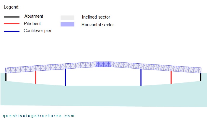
The vertical alignment consists of one horizontal and two inclined sectors. The continuous through-truss is supported by two abutments, two pile bents, and two cantilever piers. Figure 3 shows the connection between the truss and bent cap 1.
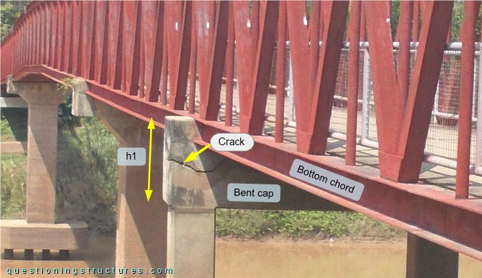
The bottom chord is partially embedded in the bent cap, and a crack under the bottom chord region is noticeable. Figure 4 shows the connection between the truss and bent cap 2.
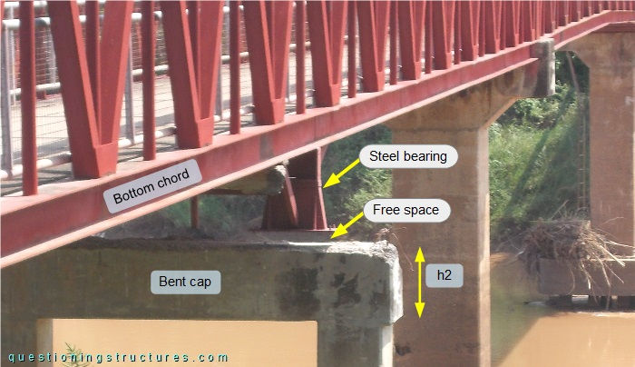
Bent cap 2 is shorter than bent cap 1 (h1 > h2), and the bottom chord is connected to a steel bearing, which is detached from the bent cap. Figure 5 shows the connections between the truss and the pier caps.
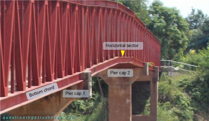
The bottom chords are partially embedded in the pier caps, and no cracks are observable.
Truss Members
Figure 6 shows a side view of a truss sector.
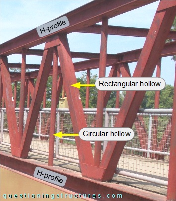
The arrangement of the web members consists of zig-zag diagonals and verticals. The upper and bottom chords are made of H-sections, the verticals are made of circular hollow sections, and the diagonals are made of built-up sections, as shown in figure 7.
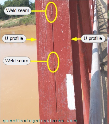
The build-up section consists of two side-by-side placed U-sections that are joined by intermittent welding.