General Information
Figure 1 shows a truss bridge that is used by motorcycles, bicycles and pedestrians.
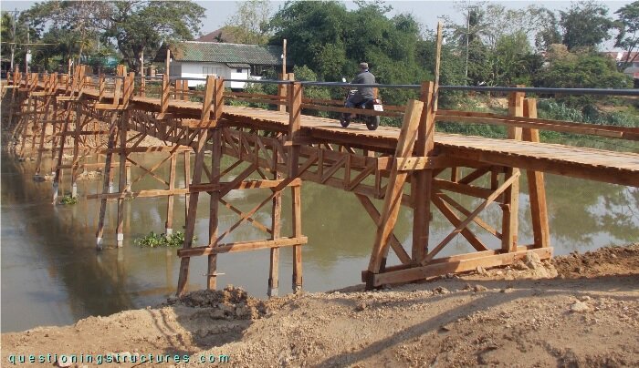
| Main span | ≅ 10 m |
| Type | Underslung truss bridge |
| Truss material | Timber |
| Truss height | ≅ 1 m |
| Deck width | ≅ 1.5 m |
Knee-Braced Timber Trusses
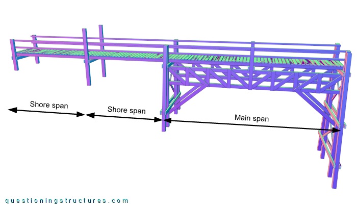
Figure 2 shows a schematic lateral view of the bridge.
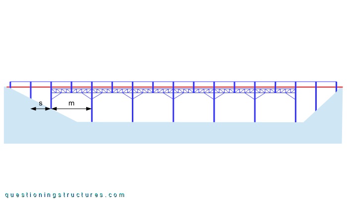
A shore span s ≅ 5 m, and a main span m ≅ 10 m. The shore and main spans are supported by timber trestles, and the foundation consists of RC piles. Figure 3 shows a main span.
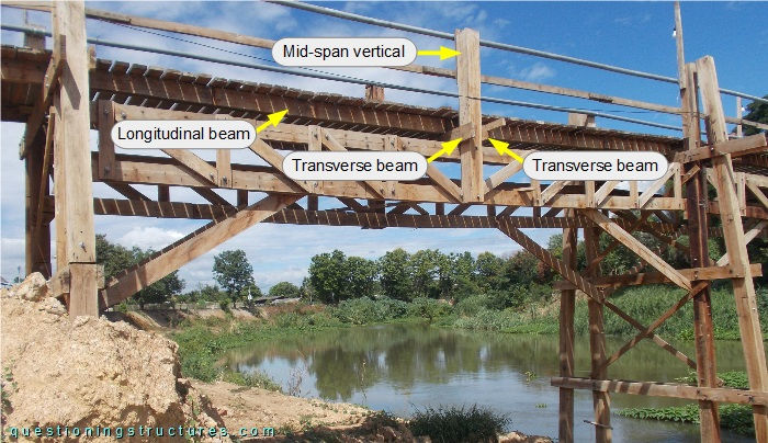
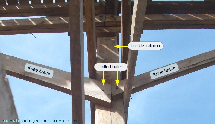
A main span consists of two knee-braced trusses, two transverse beams, two longitudinal beams, and transverse decking. The knee-braced trusses and the longitudinal beams are connected by the transverse beams (mid-span region). The mid-span vertical has a larger cross-section and is also used as a barrier post, as shown in figure 4.
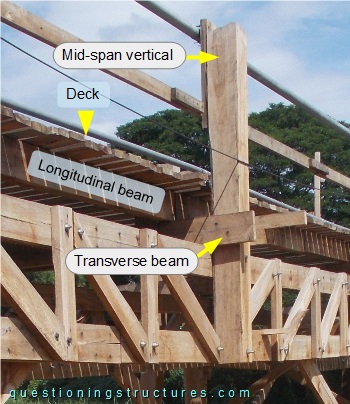
Figure 5 shows a knee-braced truss sector viewed from above.
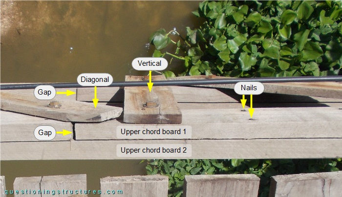
The upper and bottom chords consist of two side-by-side placed boards transversely connected by nails but not longitudinally connected (gaps). The verticals and diagonals consist of a single board; they are connected to the cords on the external vertical side by bolts and nuts. Figure 6 shows a connection between a knee-braced truss and a trestle.
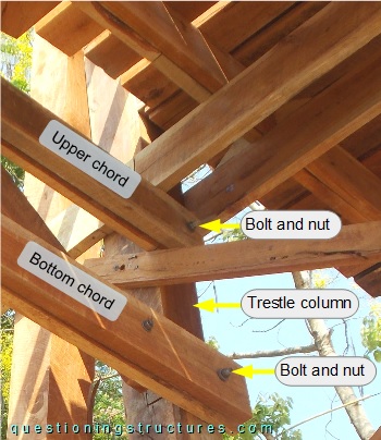
The chords are connected to the trestle's columns on the internal vertical sides by a single bolt and nut per chord. The figures below show asymmetrically arranged truss members, round holes, cracks, missing connections, and buckling deformation.
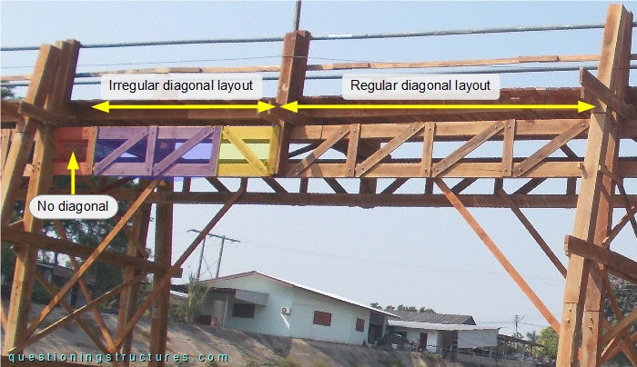
The diagonal layout is asymmetric, and there is a field without diagonal.
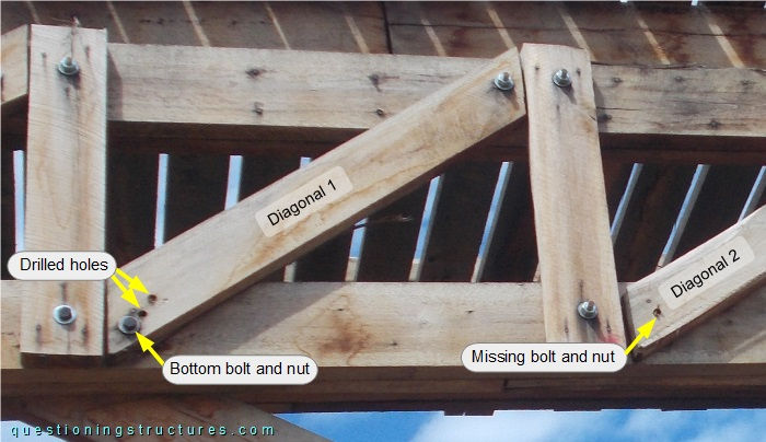
The bottom nut and bolt of diagonal 1 are placed near the edge, and two round holes are near them. Diagonal 2 does not connect the bottom chord (missing bolt and nut).
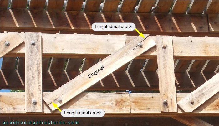
Longitudinal cracks are noticeable (connections regions).
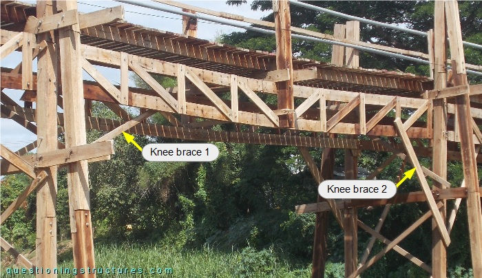
Knee braces 1 and 2 are different in size, inclination, and bottom chord connection position (internal and external sides).
The knee braces and the trestle column are not connected, as bolts and nuts are missing.
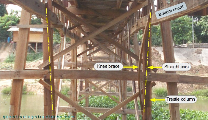
Buckling deformation is noticeable, especially on the marked brace.
How efficient are the knee-braced trusses?
Main Span Variant
Figure 13 shows a schematic three-dimensional view of a bridge sector.
A shore span consists of two longitudinal beams and transverse decking.