General Information
Figure 1 shows a pedestrian truss bridge.
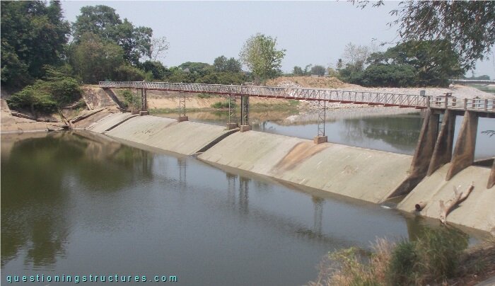
| Main span | ≅ 13 m |
| Type | Half-through truss bridge |
| Truss material | Steel |
| Truss height | ≅ 0.8 m |
| Deck width | ≅ 0.8 m |
River Discharge Forces on Piers
Figure 2 shows a side view of a steel truss pier.
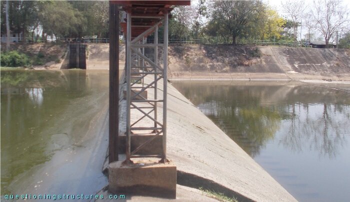
The truss is made of circular hallow sections, and the web arrangement consists of zig-zag diagonals and horizontals. Figure 3 shows the connection between the truss pier and the pedestal.
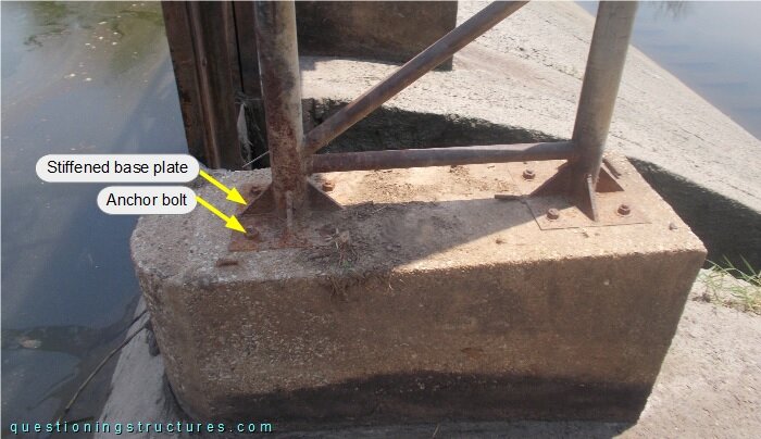
The connection consists of two stiffened base plates and eight anchor bolts (four per plate). Figure 4 shows the bridge during a high river discharge.
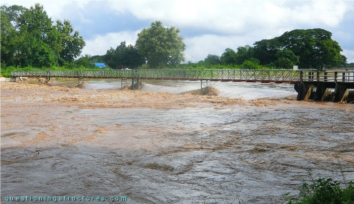
How does a river discharge change affect the piers?
Abutment Cap Failure
Figure 5 shows the abutment on shore 1.
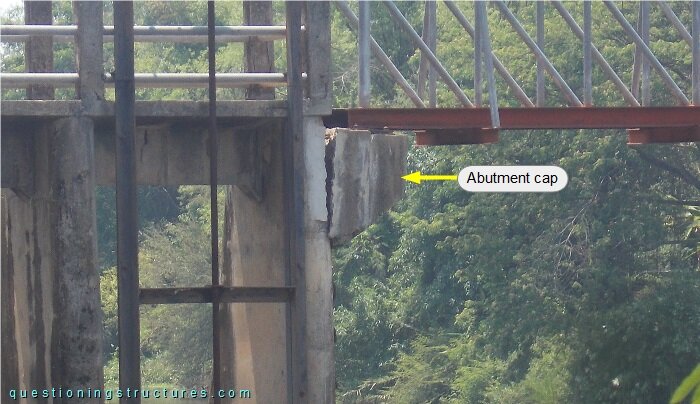
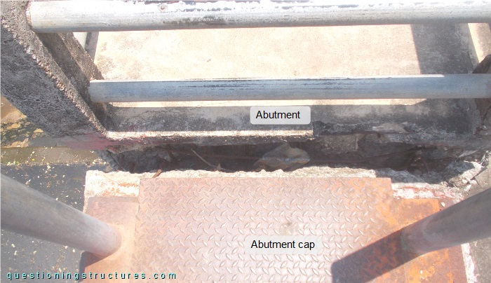
The abutment and cap are made of reinforced concrete, and the cap cantilevers. The cap detached from the abutment without causing a bridge collapse. Figure 6 shows the detached cap viewed from above, while figure 7 shows an enlarged view of it.
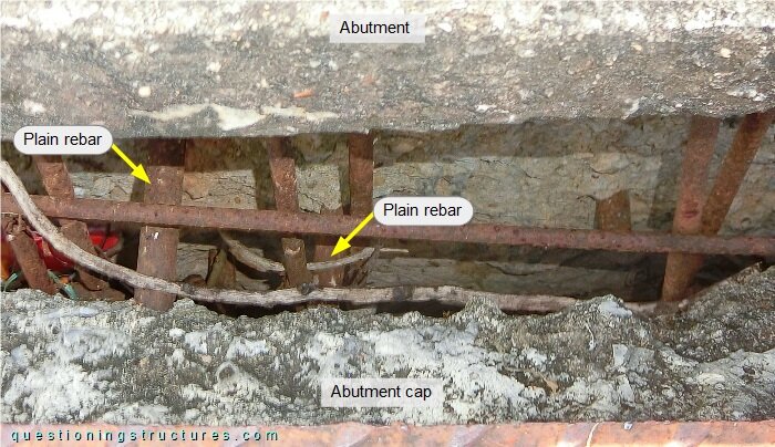
The concrete reinforcement consists of plain rebars, which are corroded. Due to the longitudinal plain rebars (two of them marked above), the abutment cap is still connected to the abutment.
Does the abutment cap still fulfill the structural safety and serviceability requirements of the bridge?