General Information
Figure 1 shows a pedestrian flyover.
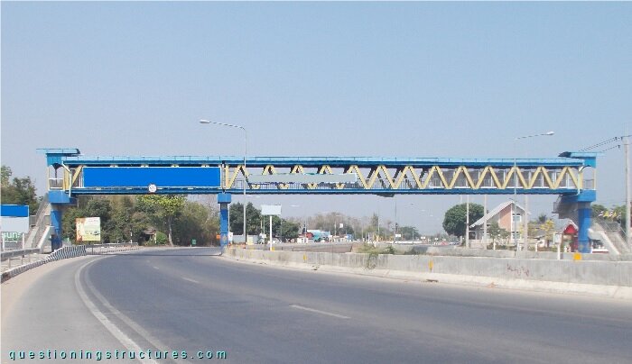
| Main span | ≅ 35 m |
| Type | Through-truss bridge |
| Truss material | Steel |
| Truss height | ≅ 2.5 m |
| Deck width | ≅ 2 m |
Truss Members
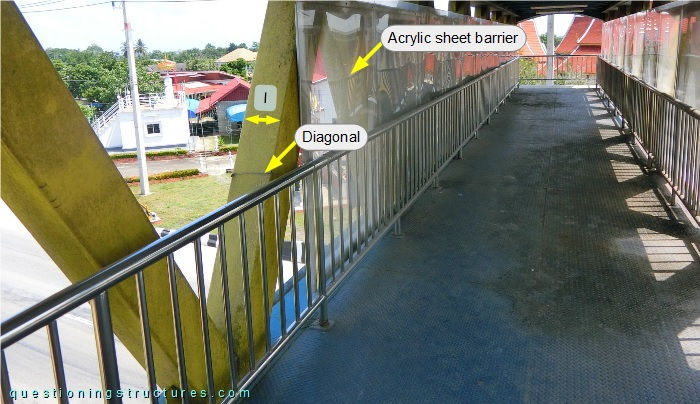
Figure 2 shows the bridge.
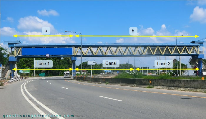
Span a ≅ 13 m, span b ≅ 35 m, and the through-truss is non-continuous. Acrylic sheet barriers are installed over the two highway lanes, while not installed over the canal. Figure 3 shows a schematic three-dimensional view of a truss sector of the main span.
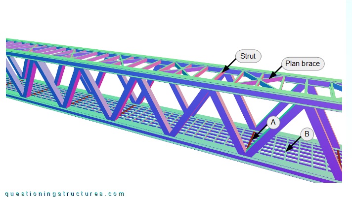
The upper and bottom chords are made of build-up sections, while the web members are made of square hollow sections; the arrangement consists of zig-zag diagonals with vertical end-posts. The floor arrangement consists of two floor beam types (A and B) and stringers. Floor beams A (shown in red) are made of U-sections and installed in every bottom node, while floor beams B are installed between the A types and are made of lipped channels. The stringers are made of L-sections and the floor system is framed. The upper level arrangement consists of struts and plan braces made of U-sections; the plan braces are installed alternately. Figure 4 shows a floor sector viewed from below.
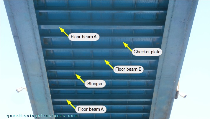
The deck is made of steel checker plates. Figure 5 shows an upper plan arrangement sector viewed from below.
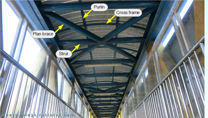
The roof structure consists of cross frames with curved rafters, purlins, and metal roofing sheets. The cross frames and purlins are made of rectangular hollow sections. Figure 6 shows a main span sector viewed from the deck.
The diagonals have an outer side length (l) of about 25 cm. The build-up section used for the upper and bottom chords is shown in figure 7.
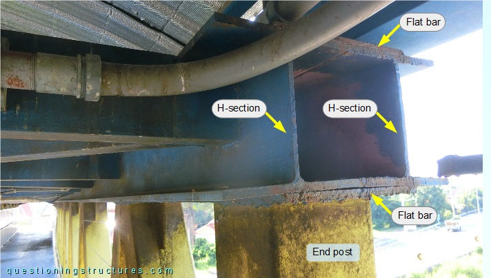
The build-up section consists of two side-by-side placed H-sections and two flat bars, which are installed over and under the H-sections. The build-up section has a height of about 25 cm.
How do the acrylic sheet barriers affect the truss design?
Consider only the structural safety (without deflection limits) with pedestrian loads. Are the diagonals and the chords probably under, over, or standard-designed?