General Information
Figure 1 shows a single lane truss bridge.
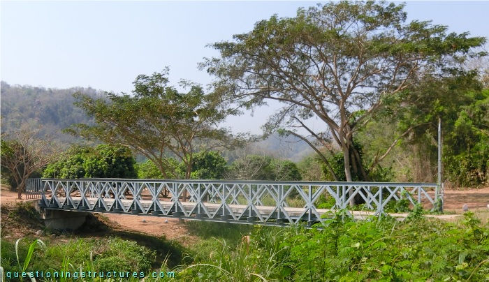
| Main span | ≅ 24 m |
| Type | Pony truss bridge |
| Truss material | Steel |
| Truss height | ≅ 1.8 m |
| Deck width | ≅ 2.5 m |
Web Member Arrangement
Figure 2 shows a side view of the bridge.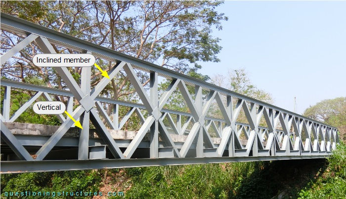
The upper and bottom chords are made of two side-by-side placed U-sections, while the web members are made of single U-sections. The arrangement consists of verticals and inclined members; the latter form a rhombus-like pattern. Figure 3 shows a schematic model of the truss and a variant of it.
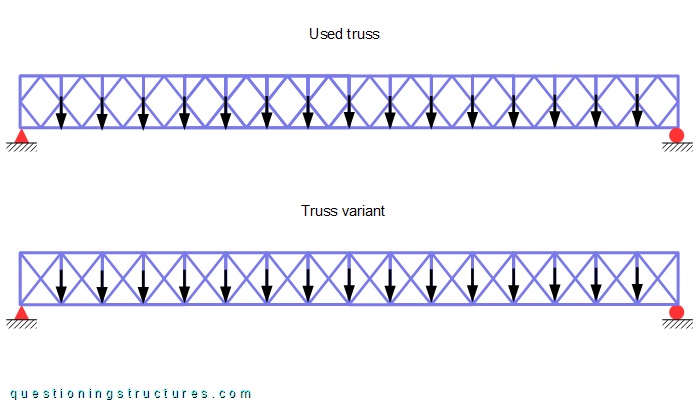
The web member arrangement of the variant consists of verticals and diagonals; the latter form an X-like pattern. Both trusses are simply supported, and the black arrows represent vertical forces acting on the bottom nodes.
What are some possible reasons for the used web member arrangement?
Floor Beams
Figure 4 shows a bottom view of the bridge.
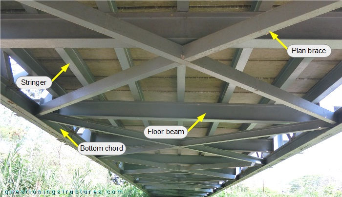
The floor system is stacked; it consists of floor beams (placed over the bottom chords) and stringers made of I-sections. The plan braces are made of U-sections; they are connected to the bottom chords and installed along the entire span. The deck is made of prestressed concrete slab planks, over which is installed an RC layer. Figure 5 shows a side view of the bridge.
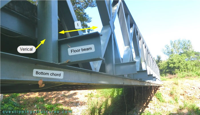
The floor beams are installed beside the verticals and overhang from the bottom chords; the overhang length l ≅ 40 cm.
How do the floor beams beside the verticals affect the truss design?