General Information
Figure 1 shows a pedestrian truss bridge.
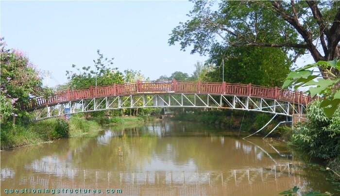
| Main span | ≅ 24 m |
| Type | Deck truss bridge |
| Truss material | Steel |
| Truss height | ≅ 1 m |
| Deck width | ≅ 1 m |
Mid-Width Verticals
Figure 2 shows a schematic lateral view of the bridge.
The girder has a slight curvature, and the rise r ≅ 1.3 m. The deck is made of timber planks; the mid-span region is horizontal and 0.5 m wider. The girder consists of chords, verticals, diagonals (upward-sloping toward the mid-span), cross-members, and braces. Figure 3 shows a truss sector.
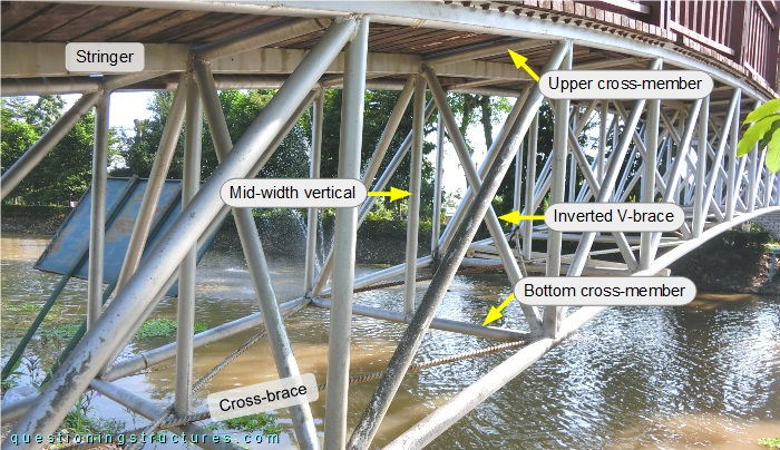
The stringers are made of rectangular hollow sections, the plan cross-braces are made of rebars, and the remaining members are made of circular hollow sections. Mid-width verticals are installed along the entire span; they are connected to the bottom cross-members, the upper cross-members, and the inverted V-braces. Figure 4 shows a stringer to upper cross-member connection.
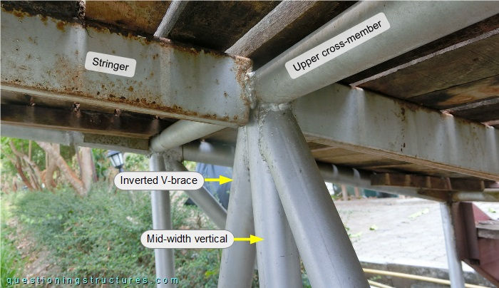
The stringer is welded directly to the upper cross-member.
Pedestrian-Induced Vibration
Figure 5 shows a lateral view of the bridge in the support region.
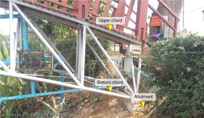
The bottom chords are connected to the abutments by base plates and anchor bolts. Figure 6 shows a schematic lateral view of the bridge.
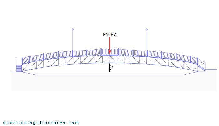
The red arrow (F1/F2) represents dynamic foot forces of a single person with open legs acting in the mid-span region, as shown in figure 7.
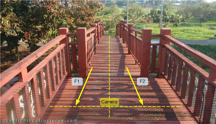
The excitation is as follows: when F1 is maximal, then F2 ≅ 0; when F2 is maximal, then F1 ≅ 0; synchronize F1 and F2 with the dynamic response. Video 1 shows the vibration with the camera placed on the deck (mid-width axis).
What is a possible frequency (Hz) assumption of the above shown vibration?
Is a structural safety problem due to pedestrian loads possible?
Which are the main factors (except F1 and F2) that affect the above shown vibration?