General Information
Figure 1 shows a pedestrian truss bridge.
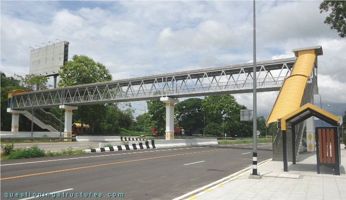
| Main span | ≅ 19 m |
| Type | Through-truss bridge |
| Truss material | Steel |
| Truss height | ≅ 2.5 m |
| Deck width | ≅ 2 m |
Hollow Structural Sections K-Connection
Figure 2 shows the bridge.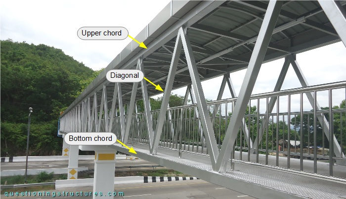
The web members' arrangement consists of zig-zag diagonals and vertical end posts; the chords and the web members are made of square hollow sections, and the truss is non-continuous (3-span truss). Figure 3 shows a schematic three-dimensional view of the connection between the diagonals and the upper chord (K-joint).
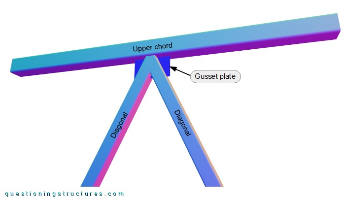
The ends of the diagonals are cut (two planes) and slotted. A rectangular gusset plate (longitudinally oriented) is welded at the mid-width of the upper chord's under side; the slotted diagonals are fitted to the mating gusset plate and connected by welding. Figure 4 shows a K-joint.
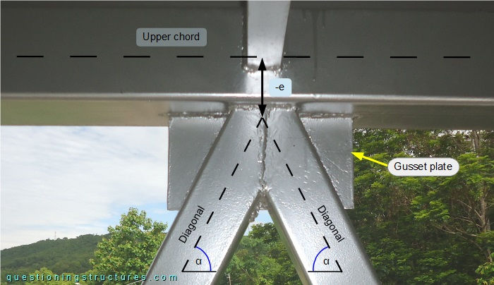
The diagonals have an inclination angle (α) of about 64° and are smaller than the chords; the double-ended arrow (-e) indicates joint eccentricity.
Figure 5 shows a schematic lateral view of the K-joint and two further configurations.
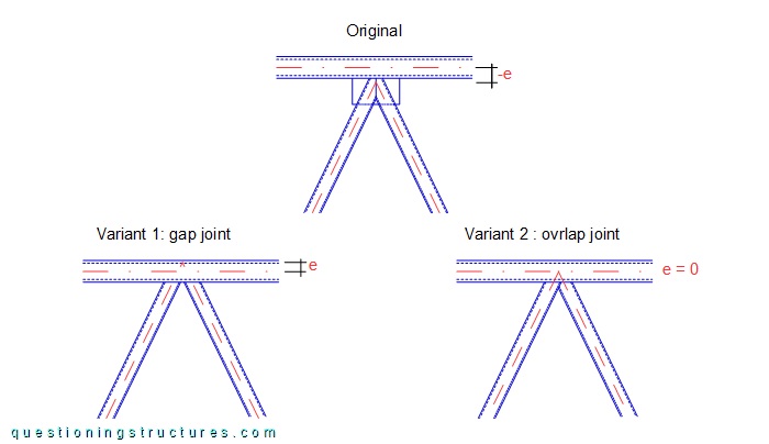
Variant 1 consists of a gapped K-joint with positive eccentricity (e), while variant 2 consists of an overlapped K-joint with zero eccentricity (e = 0). Both variants have slotless diagonals.
Which factor(s) lead to the original K-joint configuration?
Figure 6 shows a further connection viewed from below.
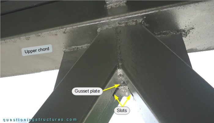
In K-joint (2), the gusset plate is shorter than the slots.
Does K-joint (1) structurally behave like K-joint (2)?